TM 11-6625-444-14-2
Section II. LOGIC CIRCUIT DESCRIPTION
The outputs from A2-U57 are then directed to
5-7. Introduction
the range encoder, A 2 - U 6 7 , an eight-line to
three-line priority encoder. In parallel with these
This section contains detailed circuit descrip-
inputs, are range command signals from the re-
tion of the range, function and dc ratio logic cir-
uits of the voltmeter. It includes logic truth ta-
mote input connector and the auto range de-
bles to aid in locating and isolating a logic mal-
coder, U52. Depending on the "logic state" of
function to a specific integrated circuit. Refer to
A2-U57, pin 9 and 2, either manual, remote or
t h e range and function selection diagrams,
autor ange commands will be selected.
g i v e s timing relationships that are helpful in
understanding the analog-to-digital conversion
process.
The three-line output of range encoder, A2-
U67 is then applied through inverters to another
decoder, A2-U250. There are really four input
lines to A2-U250 but the "D" input is fixed at
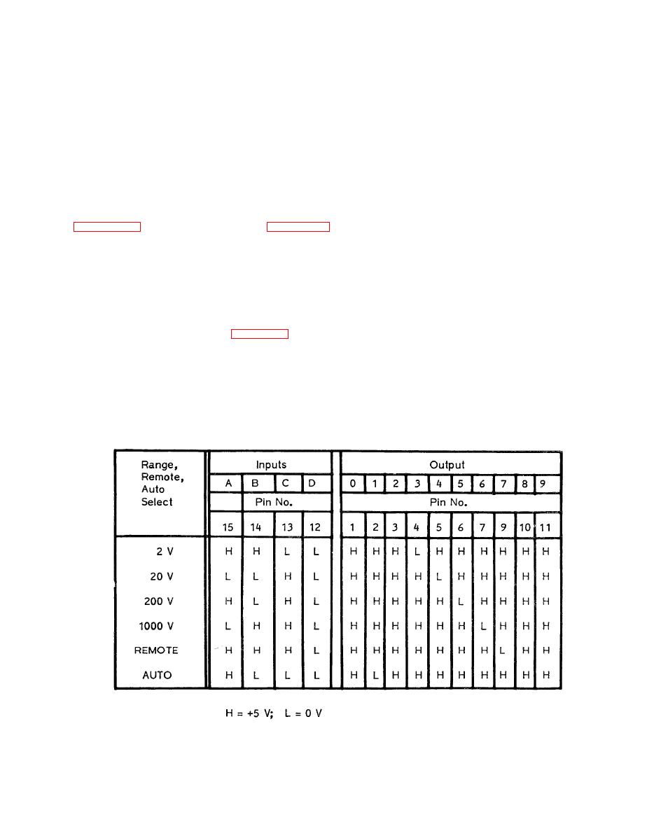
To understand the range logic flow, refer to
ground and thus; is always at a logic "low". This
the Range Selection diagram, figure 5-1 and ta-
bles 5-4, 5-5, and 5-6. Manual inputs are ap-
input logic to A2-U250 then selects one of the
plied through the front panel push buttons to
output lines to be "low". The "low" output line
A2-U57, the manual range decoder. This is a
from this decoder determines which range has
four-line BCD to ten-line decimal decoder.
been selected.


