TM 11-6625-444-14-2
NOTES:
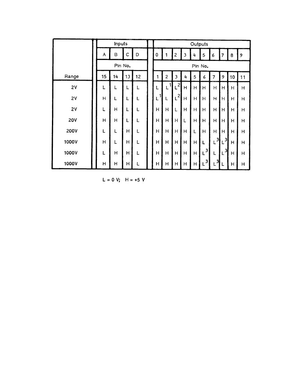
1. Pins 1 and 2 are connected together
2. Low because of "NAND" gate U61B
3. Pins 6, 7, 9 are connected together
a "high" at U50A pin 3, In Voltage mode, a logic
The clock pulses from the Timer, U60 pin 9,
"high" is also present at pin 2; thus a "low" at
are applied to pin 15 of the U/D Counter. These
pin 1. This disables U50C NAND gate and as a
clock pulses have a rate of 4 Hz (one pulse
result; the Up/Down Counter.
every 250 milliseconds) and time the BCD output
of the Autorange U/D Counter. This provides
the Q1, Q2 and Q3 inputs to the Autorange De-
When the
coder U52 (A, B, C respectively).
AUTO (range) mode is selected, a logic, "low" is
connected to U52 pin 12, providing the "D" in-
When no remote input range is selected, (all
put.
remote lines "high") the output of NAND gate
U643 (pin 6) is "low". This "low" is applied
through an inverter, becoming a "high", to NAND
gate U6113 pin 11. In REMOTE mode, the other
Down Range Command: When a logic "high"
gate input (pin 12) is also "high" resulting in a
(Down Range command) is applied to U50C pin
"low" out. This output is connected to the "Auto
9, a logic "low" is then at the output (pin 10).
This "low" enables the U/D Counter. Because a
Enable" input (pin 12) of the Autorange Decoder,
U52 (which requires a "low" to enable) and puts
"low" is at U51 pin 10, the down-count mode is
the voltmeter in the remote autoranging condi-
selected. When autoranging has ranged down to
tion.
the 2 V range, a logic "low" is at U54 pin 11 and


