TM 11-6625-444-14-2
b. Ratio Differential Amplifier. A dc reference
o f the ratio differential amplifier, A9-U1, is
voltage of either plus or minus polarity is con-
always a positive voltage. The polarity sign of
netted to the RATlO (EXTERNAL REFERENCE)
the displayed percent ratio will always be the
rear input terminals. Polarity detector A9-U54A
algebraic equivalent of the input signal divided
will reverse the polarity of a negative reference
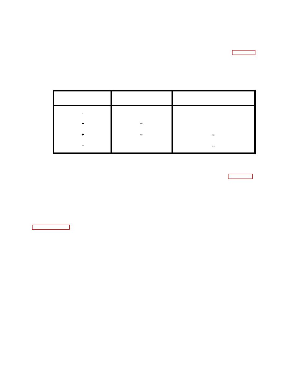
by the reference signal. Refer to table 5-2.
v o l t a g e by actuating relay A9-K16 so the output
External Reference
Displayed
Input Signal
Polarity
Polarity
Polarity
+
+
+
+
+
A9-U1 has unity gain for reference voltages up
the auto ranging circuits. See table 5-3 for a
to 10.5 V but changes automatically to a gain of
listing of ratio ranging possibilities.
0.1 for reference voltages between 10.5 and
100 V; thus the maximum full scale output of the
ratio differential amplifier is +10.5 volts.
a. The resultant analog dc signal from the A/D
buffer, AI-U 104, is applied to the analog to dig-
ital (A/D) converter. Here it is compared to a
c. The ratio voltage is then applied through
+10 V reference if the input signal is positive or
active filter A9-U100 (similar to that described in
to a -10 V reference if the input signal is nega-
tive (dc voltage mode only; its polarity auto-
amplifier, A9-U450. A9-R452, the RATIO FULL
m a t i c a l l y detected and displayed by the A/D
RANGE control, permits slight gain adjustments
converter. The analog signal is converted to a
(less than/more than unity) of this amplifier so
digital signal that is equivalent to 199,000 counts
that when the reference voltage equals the input
from the 12 MHz clock for a full scale reading,
voltage; the displayed ratio reading can be rror-
each time a sample reading is taken by the digi-
malized to 100.0007.
A voltage measurement that is
tal counter.
one-tenth the full scale range results in a count
d. Ratio Autoranging Operation. The ratio
of 20,000 when a sample reading is taken.
amplifier voltage is then compared with the dc
input voltage in the ratio up/down detectors,
b. The sampled pulses are applied to digital
A1-U402 and U401 respectively. The output of
counters (A2-U354 through U358) and then sent
the detectors, is an "up range command" for ra-
to the 5 digit display (A3) where they are pre-
tio counts higher than 180,000 or a "down range
sented as a voltage or ratio reading with polarity
command" for ratio counts lower than 14,000
which is then applied to the up/down counter,
automatically indicated. The count is also con-
A2-U51. This determines how many pulses from
verted to BCD and made available for external
the auto range clock, A2-U60, are processed by
processing at the rear panel.


