TM 11-6625-444-14-2
attenuates the input signal by 40 dB. The gain of
(A7-Q4A,B through A7-Q10,11). If the ac+dc
the preamplifier/scaler is changed by altering
mode is selected, then the signals are directly
the feedback resistors.
On the 2 and 200V
coupled to the preamplifier/scaler by the ener-
ranges, the gain is unity; on the 20 and 1000V
gizing of relay A7-K1. Relay A7-K2 connects
ranges the gain is reduced to 0.1 (-20 dB).
A7-R8 to ground when it is in the "on" state
Refer to table 5-1 for ac attenuation. A7-R23,
(200 and 1000V ranges) and provides a 100:1
AC NULL, balances the preamplifier for a zero
v o l t a g e divider in conjunction with the input
This
input signal condition.
R 1 , R2, R3 and R4.
resistor string;
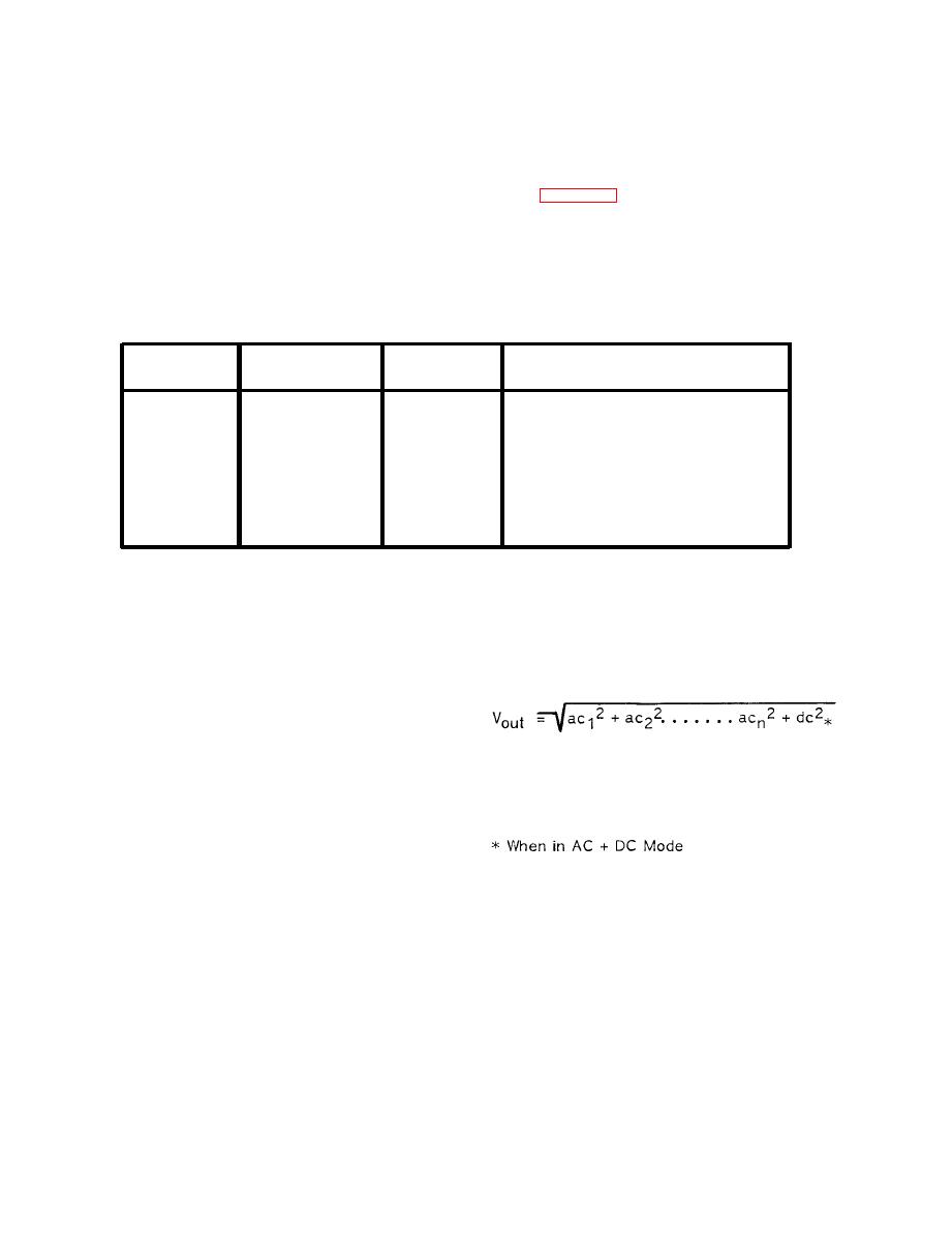
Table 5-1. Ac Attenuation
Total
Input
Preamplifier
Gain
Range
-20 dB
60 dB
40 dB
1000V
0 dB
40 dB
40 dB
200V
20 dB
-20 dB
20V
0 dB
0 dB
0 dB
2V
0 dB
age. For a 2 Vrms input at the front panel ter-
c. True Rms Converter. The ac output signal
from the preamplifier/scaler is next applied to an
minals, the dc output from U7 will be 2 Vdc. The
a c t i v e precision rectifier, A7-U1, through a
transfer function of the true rms converter cir-
switchable low pass filter that produces a -3 dB
cuits is described by the following formula:
rolloff at 10 kHz. The half-wave output of the
active rectifier is then combined with the ac sig-
nal (reduced to half that of the rectified signal)
and the combined signal is directed to the sum-
ming amplifier, A7-U2. The output of the sum-
ming amplifier is a negative going, full-wave
Where Vout = The dc equivalent of the applied
rectified signal.
T h e rms converter module
rms voltage.
(A7-U3) is in the feedback loop of the summing
amplifier and the feedback current is proportion-
a l to the output voltage of U2.
Thus, U2
provides a voltage-to-current conversion that
drives the input of the rms module.
This Vout dc signal is then directed to the dc
The output current (pin 7) of the rms module
buffer amplifier, A1-U1, and processed exactly
is fed to amplifier A7-U4, a current-to-voltage
t h e same as a dc signal (Dc Measurement
converter. The output of U4 is then applied to
Mode).
high impedance buffer amplifier A7-U7 through a
three section, active filter A7-U6. U7 has a
voltage gain of 2X, offsetting the loss in U2. In
the NORMAL mode, the active filter operates
down to 40 Hz and has a response time of 300
ms. When the switch is pushed in to the SLOW
a. The dc ratio mode of operation is the same
RESPONSE position, the filter operates to as low
as the dc measurement mode except that the dc
as 0.5 HZ with a response time of less than 30
voltage applied to the front panel input terminals
seconds. The rms converter produces a dc volt-
is compared to a reference voltage applied to
age exactly proportional to the rms input volt-
the rear panel EXTERNAL REFERENCE terminals.


