TM 55-4920-231-14
d. Reassembly.
(3) Solder wiring harness leads on trans-
(1) Insert lamp (25, figure 22) in light
former (6, figure 24) rectifier (4), and power
base (24) and turn clockwise to secure.
switch (15). Refer to figure 10 for color codes.
(2) Install cap (26) on light base.
(4) Attach plug connector (21, figure 24)
and install chassis assembly in tester case (para-
graph 73).
85. WIRING HARNESS.
Repair the wiring harness by relpacing a de-
86. POWER CABLES.
fective lead or replace harness as follows:
The power cables (9, 10, 13, and 14, figure 3)
a. Removal.
are inspected and repaired or replaced as fol-
(1) Remove chassis assembly (figure 24)
lows:
from tester case (paragraph 73a) and disconnect
a. Inspection.
plug connector (21).
(1) Inspect the cable assemblies for cracks,
(2) Unsolder wiring harness leads on trans-
breaks, cuts, distortion, and damaged threads.
former (6), rectifier (4), and power switch (15).
(2) Test the cable assemblies for continui-
(3) Remove nut (39, figure 25) and screw
ty (figure 10).
(41), securing ground leads to chassis (51).
(3) Perform a high potential test on each
(4) Remove wiring harness (4) and grom-
cable assembly, Refer to Military Specification
mets (50) from chassis (51).
MIL-C-5015.
b. Installation.
b. Repair or Replacement.
(1) Install grommets (50, figure 25) and
(1) When replacing wire or connectors, use
identical parts.
insert wiring harness (4) in chassis (51).
(2) Insert screw (41), install ground leads
(2) Replace a defective cable assembly that
cannot be repaired.
and secure with nut (39).
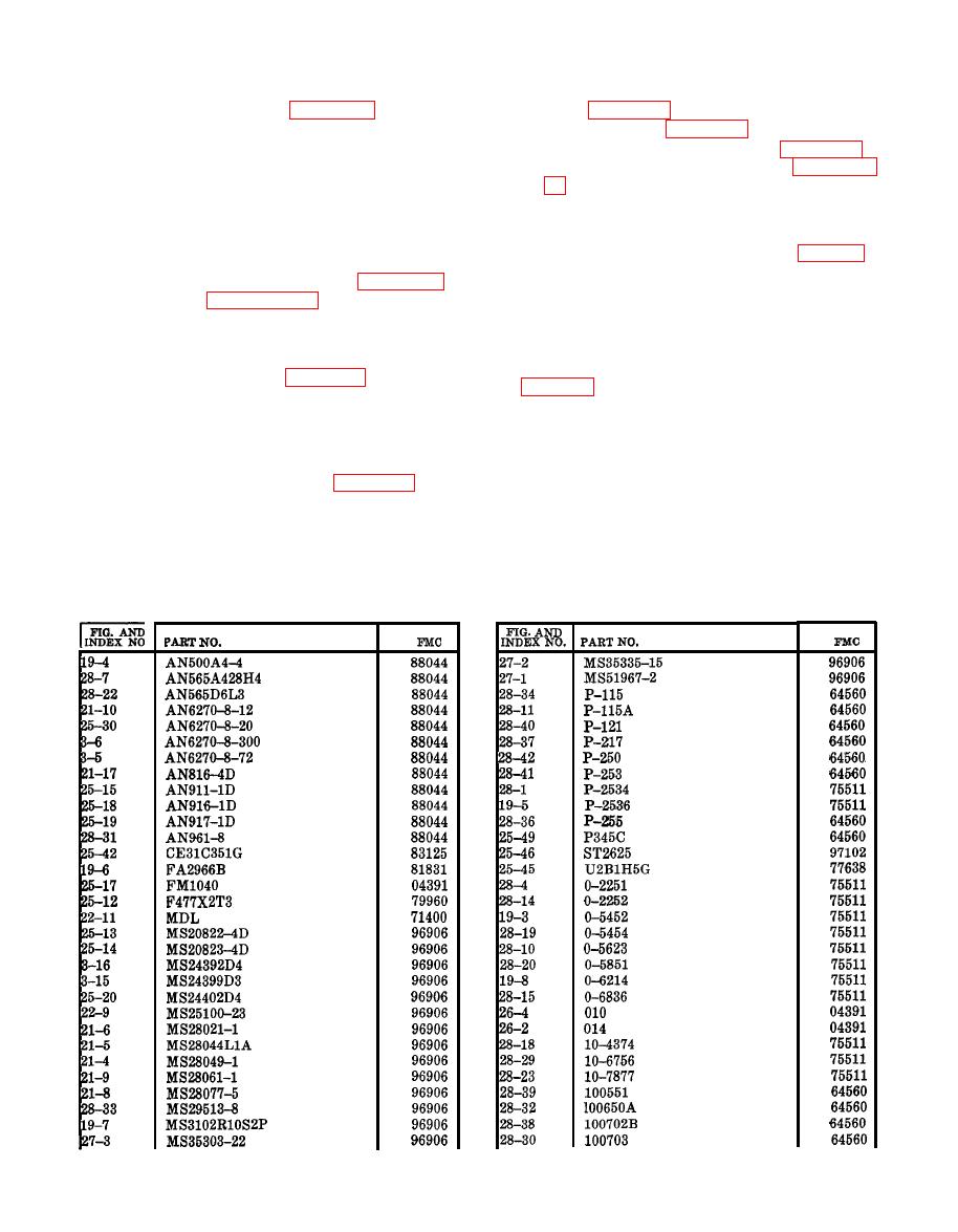
Section VIII. NUMERICAL PARTS LISTING


