TM 55-4920-231-14
DS AND GS
MAINTENANCE INSTRUCTIONS
Section I. SPECIAL DS AND GS REPAIR PARTS
No special tools are required for DS and GS
The repair parts required for DS and GS
maintenance of the tester.
maintenance of the tester are listed in section
NOTE
VII of Repair Parts and Special Tools Listing,
Lubrication of the tester is described in para-
Section II. TROUBLESHOOTING
89. GENERAL.
90. TROUBLESHOOTING.
This section provides DS and GS maintenance
A tabulation of symptoms of probable trou-
bles and remedies which are likely to be en-
personnel with information useful in diagnosing
countered before, during, or after operation and
and correcting failures of the tester.
repair of the equipment are contained in table 6.
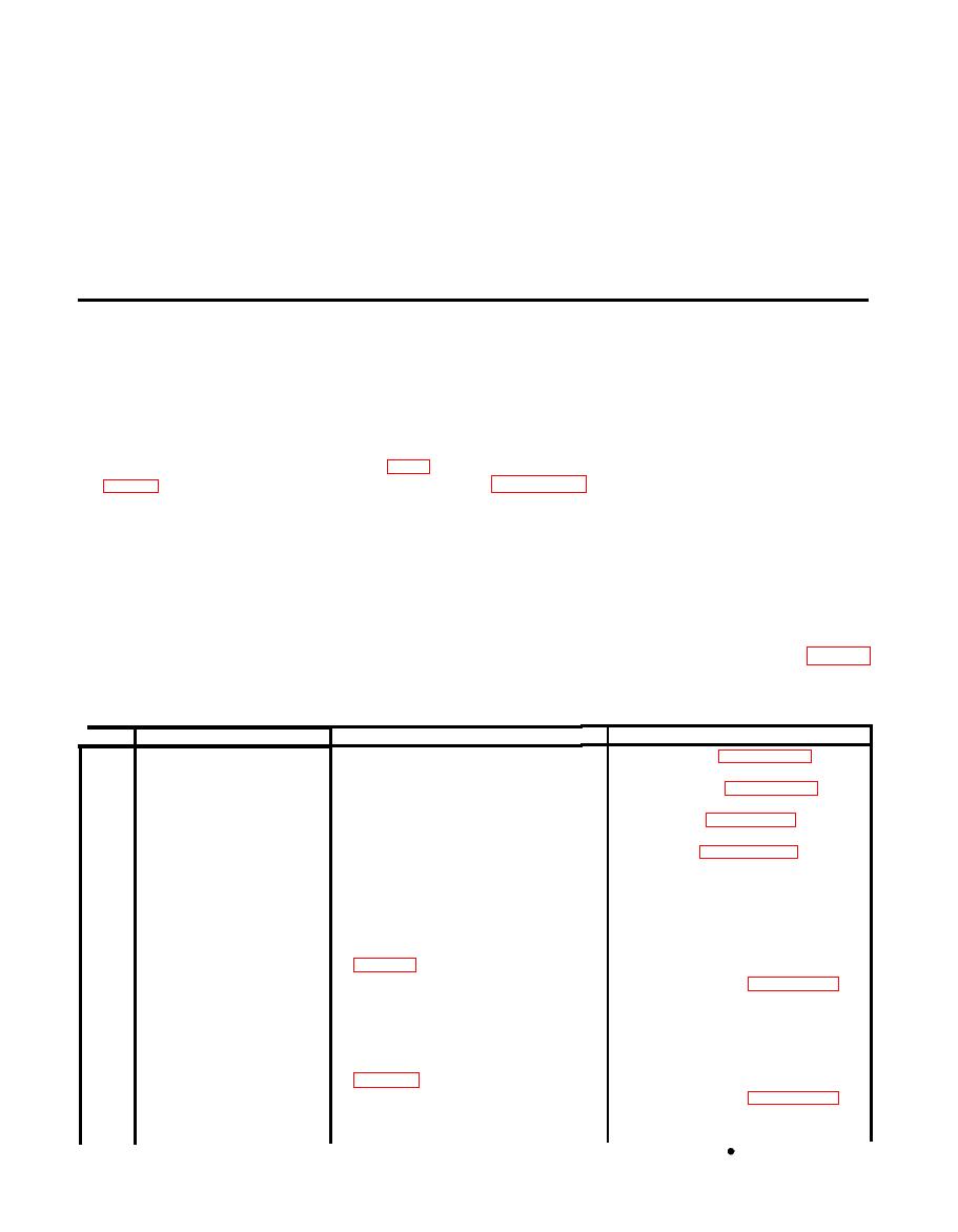
Table 6. Troubleshooting
Possible remedy
Trouble
Item No.
Probable
cause
Replace rectifier (paragraph 80).
1
Indicator light does
Open rectifier or shorted ca-
pacitor and motor. (Check
not illuminate and
Replace capacitor (paragraph 98).
voltage on yellow coded lugs of
motor does not run when
power switch is in ON
rectifier.) If voltage is present with
Replace motor (paragraph 81).
no dc voltage acrosss the red
position.
and black coded lugs, either the
Repair motor (paragraph 100).
the rectifier is open or capacitor
or motor is shorted. Disconnect red
lead from the rectifier and re-
check voltage across red and
black coded lugs of rectifier.
If dc voltage is now present, capacitor
or motor is shorted. (See
Replace transformer (paragraph 99).
Open transformer primary winding
cm input leads. (Disconnect plug
mating with J1 and check re-
sistance between pins 1 and 2 at
T1. Resistance check on J1
between pins I and J; see
Replace transformer (paragraph 99).
Open transformer, secondary winding.
Check voltage across terminals 3
and 4 of T1, 25V(rms).


