TM 11-6625-2616-14
screws extending from the module through the
circuit board until the end of the screws are
flush with the bottom of the circuit board.
(5) Grasp the module and carefully pull it
away from the circuit board.
(6) Carefully insert the new module into
position making sure that the leads are properly
aligned. Note that the decal on the module can
be read when facing the front of the instrument.
(7) Replace washers and nuts. Tighten nuts
evenly in a rotating manner until they are snug.
d. Integrator Amplifier, Null Amplifier, and
Reference Supply Replacement.
(1) Remove power cord from power outlet,
fuse holder, top and bottom covers, top and bottom
shields (a(1) through a(4) above).
(2) Perform the steps set forth in c(2)
t h r o u g h c(7) above, noting however, that
these three modules are attached to the main
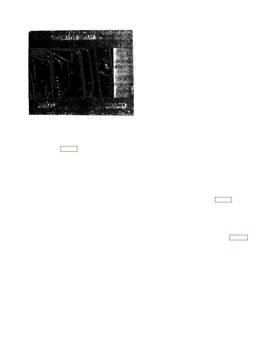
(3) The integrated circuit package consists
printed circuit board.
of three parts: the integrated circuit, the retainer,
and the socket (fig. 7-3).
e. Signal Conditioning Board Removal.
(4) Carefully grasp the faulty or suspected
(1) Remove power cord from power outlet,
integrated circuit at each end (use a standard
top cover, and top shield (a(1), a(3), and a(4)
pair of pliers or thumb and forefinger) and
above).
gently pull straight upward and away from the
(2) Place signal conditioning board in up-
socket.
right position (a(5) above).
CAUTION
(3) Remove the two nuts and washers at-
Do not use a twisting or rocking motion
taching the main board ribbon cable connector
as this will most likely bend the leads.
to the signal conditioning board (fig. 7-4).
(5) Remove the retainer and place it on the
(4) Carefully pull the cable connector away
new integrated circuit.
from the underside of the signal conditioning
(6) Carefully insert the new integrated cir-
board.
cuit into the socket. Be sure the leads are properly
(5) Place the signal conditioning board flat,
aligned and that the index mark on the end of
in its normal operating position.
the integrated circuit is toward the index mark
(6) Remove clamp attaching nut (fig. 7-4)
on the printed circuit board at one end of the
and remove clamp.
socket.
(7) Remove solder lug attaching nuts (fig.
c. Buffer Amplifier and Input Attenuator Re-
7-4) and remove solder lugs. Tag one of these
placement.
lugs for identification.
(1) Remove power cord from power outlet,
(8) Remove signal conditioning board.
top cover, and top shield (a(1), a(3), and a(4)
above).
f. Readout Tube Replacement.
(2) Place signal conditioning assembly in
(1) Remove power cord from power outlet,
upright position (a(5) above) and place the in-
fuse holder, and top and bottom covers (a(1)
strument on its side.
through a(3) above).
(3) Remove the four screws and washers
(2) Remove bezel and front panel (a(6)
attaching these modules to the signal condition-
above).
ing printed circuit board.
(4) While holding the printed circuit board
(3) With a rocking motion, carefully pull
steady, carefully press evenly against the four
the faulty tube from its socket.


