TM 11-6625-2616-14
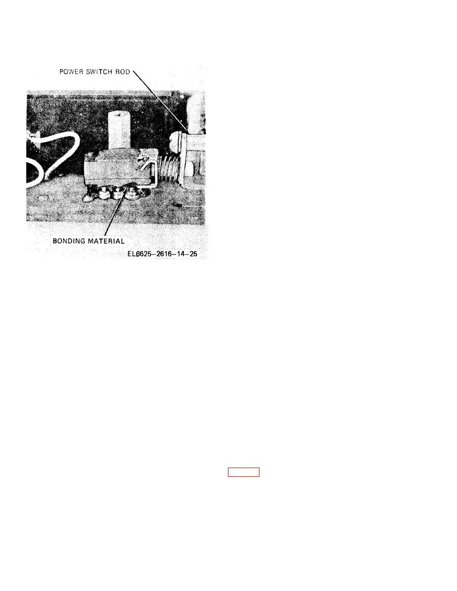
cuit Boards); manufacturer is Dow Corning Cor-
poration, South Saginaw Road, Midland, MI
48640; manufacturer's designation is 3140RTV.
The material is available in three-ounce, self-
dispensing, collapsible tubes.
(3) To replace a defective component sol-
dered and bonded to the circuit board, perform
the following steps.
(a) With a sharp knife, cut away as much
of the bonding material as possible from the
defective part and its solder pads. Use care not
to damage the printed circuitry or the solder pads.
(b) Apply additional solder to the corn-
ponent leads and to the solder pads on each side
of the board. This application of solder destroys
the bonding material and re-tins the solder pads.
(c) Heat solder on component leads and
pads and remove with a solder sucker. Inspect
leads and pad area to make sure leads are loose.
(d) Components may still be attached to
the circuit board by small amounts of bonding
material; Carefully manipulate the component and
cut away the material until the defective com-
ponent is free from the circuit board.
(e) Inspect the immediate area from
where the component was removed for loose flaps
the printed circuit boards by soldering. They are
or bits of the bonding material; if found, trim
then coated and bonded to the circuit board to
the flaps and clean the area with isopropyl alcohol.
protect them and the printed circuitry from hu-
(f) Solder new component in place, in-
midity and moisture. This bonding, or post coat-
suring a firm and clean solder connection.
ing, also serves to protect the components under
conditions of vibration or shock.
(g) Apply a moderate amount of 3140-
RTV silicon rubber to the repaired area and over
(2) The coating and bonding agent used is
the new component.
a translucent, room temperature-curing silicon
rubber. Type SR per MIL-I-46058, Insulating
(h) Allow 24 hours drying time before
Compound, Electrical (For Coating Printed Cir-
operating the instrument.
Section II.
ADJUSTMENTS
7-3. General
An adjustment (or calibration) cycle of 6 months
a. Initial Preparation.
is sufficient for areas of normal operating condi-
(1) Remove fuse and top and bottom covers
tions. The calibration of any instrument changes
slightly with age, use, and operating conditions.
(2) Replace fuse.
Also, problems which may not be apparent during
(3) Plug power cord into ac outlet, ensuring
normal use will show up during a calibration
that the power selection switch is set to proper
check.
voltage.
(4) Depress PWR ON pushbutton switch.
Allow 30 minutes for instrument warmup.
DC voltage standard, John Fluke Model 332A
(5) Be sure that the VDC and AUTO RNG
(FSN 6625 -239-8924), or equivalent).
pushbutton switches are in the "in" position.


