TM 11-6625-2616-14
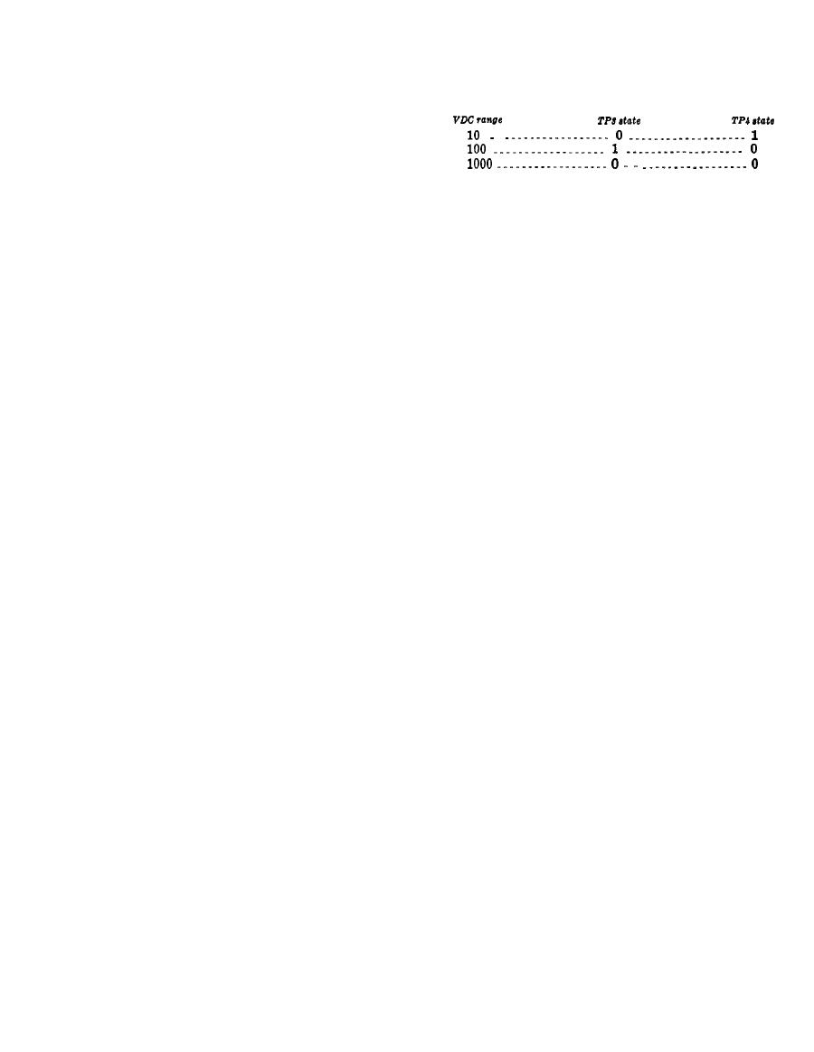
(4) The oscilloscope should indicate the
b. Test Procedure.
levels shown in the chart.
(1) Connect the oscilloscope common to in-
strument SIG L.
to TP3 on the main board assembly.
(3) Connect the oscilloscope 10:1 probe to
6-15. Range Change Pulse Width Test
TP2 on the main board assembly.
a. Test Conditions.
(4) The oscilloscope should indicate a 20-
(1) Instrument connected to 115 vac or 230
microsecond pulse at 3- to 5-volt amplitude from
vac power source.
0 to 240 milliseconds after the trialing edge
(2) PWR ON pushbutton in (no warmup
(negative going) of the pulse at TP3. Delay
required ).
between pulses is proportional to the input being
measured by the instrument. The pulse at TP2
(3) VDC pushbutton in.
is generated when the clock pulses at TP12
b. Test Procedure,
cease.
(1) Connect the oscilloscope common to in-
strument SIG L.
(2) Connect the voltage standard common
a. Test Conditions.
to instrument SIG L.
(1) Instrument connected to 115 vac or 230
(3) Connect the voltage standard output
vac power source.
to instrument SIG H.
(2) PWR ON pushbutton in (no warmup
(4) Connect the oscilloscope external trig-
required). VDC pushbutton in.
ger to TP2 on the main board assembly.
(5) Set the voltage standard output to
b. Test Procedure.
+5.0000 volts.
(1) Connect the oscilloscope common to in-
(6) Connect the oscilloscope 10:1 probe to
strument SIG L.
TP2 on the signal conditioning board.
(2) Connect the oscilloscope 10:1 probe to
(7) The oscilloscope should indicate a 20-
TP3 or TP4 on the signal conditioning assembly,
microsecond pulse at 3- to 5-volt amplitude coin-
(3) Actuate RNG CHNG pushbutton to
cident with the external trigger pulse whenever
place instrument in the ranges shown in the chart
a range change is required by the input to the
below,
instrument, If the input is increased from 5 volts
to 50 volts, the pulse will appear at TP2 on the
NOTE
"0" state corresponds to a voltage less
signal conditioning board. If the input is de-
creased from 50 volts to 5 volts, the pulse will
than + 0.4v and "l" state corresponds
appear at TP1.
to a voltage greater than +2.4v.


