TM 11-6625-2616-14
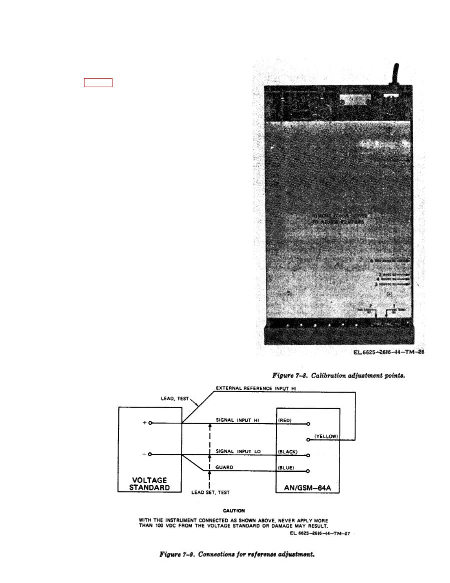
(6) It will be noted that the top shield dis-
plays the sequence numbers of calibration and the
reference designation of each adjustment poten-
tiometer (fig. 7-8).
b. Zeroing the Readout.
(1) Plug connector of test lead set into SIG
H and SIG L input jacks.
NOTE
A small polarity tab sticks out from the
connector nearest the SIG L plug; i.e.,
the tab sticks out to the left of the opera-
tor when the connector is properly in-
stalled.
(2) Insert blue plug adjacent to connector
into GUARD input jack.
(3) Connect the three clips of the test lead
set together. They are covered with red, black,
and blue protective boots.
(4) The instrument readout should display
00.0000. If it does not, adjust the ZA potentio-
meter by inserting a small screwdriver in the
opening directly underneath the VDC pushbutton
switch and turning the adjustment screw until
the readout transfers from 00.0000 to +00.0001;
observe the angle of the screwdriver blade, Back
off the adjustment until the readout transfers
from 00.0000 to - 00.0001; observe the angle of the
screwdriver blade. Now place the adjustment half-
way between these two settings.
c. Ratio Adjustment-10-Volt Reference.
(1) Connect the instrument as shown in fig-
ure 7-9.


