TM 11-6625-2616-14
(2) Power and range switch replacement.
(a) Remove power cord from power out-
let, fuse holder, and top and bottom covers (a(1)
through a(3) above).
(b) Remove bottom shield (a(4) above).
(c) Remove bezel and front panel (a(6)
above) and turn the instrument so that it rests
on the top shield.
(d) Pull front plate away from chassis
(a(8) above).
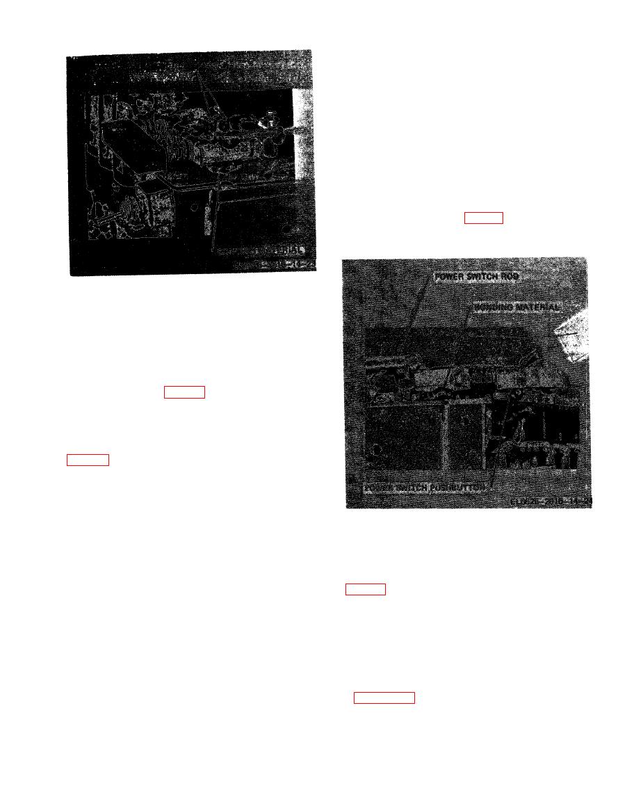
(e) Insure that the PWR ON pushbutton
is in the "out" position (fig. 7-6).
(d) Pull front plate away from chassis
(a(8) above).
(e) With a sharp knife, cut silicon rubber
away from switch pins and wire sockets on top
of switch assembly (fig. 7-5).
(f) Remove wire sockets from switch
pins.
(g) Carefully cut away the silicon rubber
bonding the switch assembly to the circuit board
both sides and in the middle of the switch assem-
bly. Due to switch assembly pins inserted into
sockets in the circuit board, it is difficult to cut
all of the silicon rubber away. After most of the
material is cut free, use a screwdriver to care-
fully and evenly pry the switch assembly away
ment.
from the circuit board, cutting the bonding mater-
ial as required.
(f) Carefully move the power switch rod
to the surface level of the plug-in sockets on the
circuit board. Clean any bits of the material
rod upward away from the coupler on the front
from the sockets or around the switch mounting
switch. Move the rod forward and away from the
area with isopropyl alcohol.
rear power switch.
(i) Squeeze a moderate amount of 3144-
(g) Remove bonding material, remove
switch assembly, and install new switch ( (1)(g)
RTV silicon rubber on plug-in side of new switch
assembly. Do not allow bonding material to get
through (1)(j) above).
on the tip of the switch pins or to enter the
(3) Rear Power Switch Replacement. Refer
sockets. Evenly press switch assembly against
to figure 7-7 and perform the steps set forth in
circuit board until pins contact the bottom of the
(2)(a) through (2)(g) above.
sockets. Observe that the bonding material is in
i. Replacement of Minor Components.
contact with the surface of the circuit board.
(1) The minor components of the AN/GSiM-
(j) Allow 24 hours drying time before
operating the instrument.
64A (capacitors, resistors, etc.) are mounted on


