TM 11-6625-444-14-2
e. Ratio < -14000 Down Range Trip Point Ad-
(5) observe that the voltage measured by
justment (A1-R402)
the digital multimeter i s approximately -15.0
Vdc.
(1) Continue with the same setup as in the
previous step.
(6) Reduce the voltage applied to the volt-
meter front panel INPUT terminals to -0.1300
Vdc.
(2) Apply a -0.1400 Vdc signal to the volt-
meter front panel INPUT terminals from the sec-
ond dc voltage calibrator.
(7) Observe that the voltage measured by
the digital multimeter is approximately +5.0 Vdc.
(3) Adjust A1-R402 until the voltage mea-
sured by the digital multimeter just trips from
approximately -15.0 Vdc to approximately +5.0
Vdc.
(4) Increase the voltage applied to the
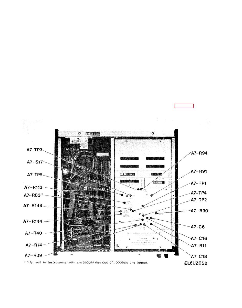
a. Zero Drift Temperature Compensation Ad-
voltmeter front panel INPUT terminals to -0.1500
justment (A7-R30). Refer to figure 6-27 for lo-
Vdc.
cation of adjustments.


