TM 11-6625-444-14-2
(7) Replace the top cover of the guard
(2) Select the 200 V range and DC/DC
cage.
RATIO function on the voltmeter.
(3) Apply a +112.0 Vdc signal from the dc
voltage calibrator to the V/LO EXTERNAL REF-
ERENCE terminals.
a. > + 195000 Up Range Trip Point Adjustment
(4) Adjust A9-R51 until the voltage at A9-
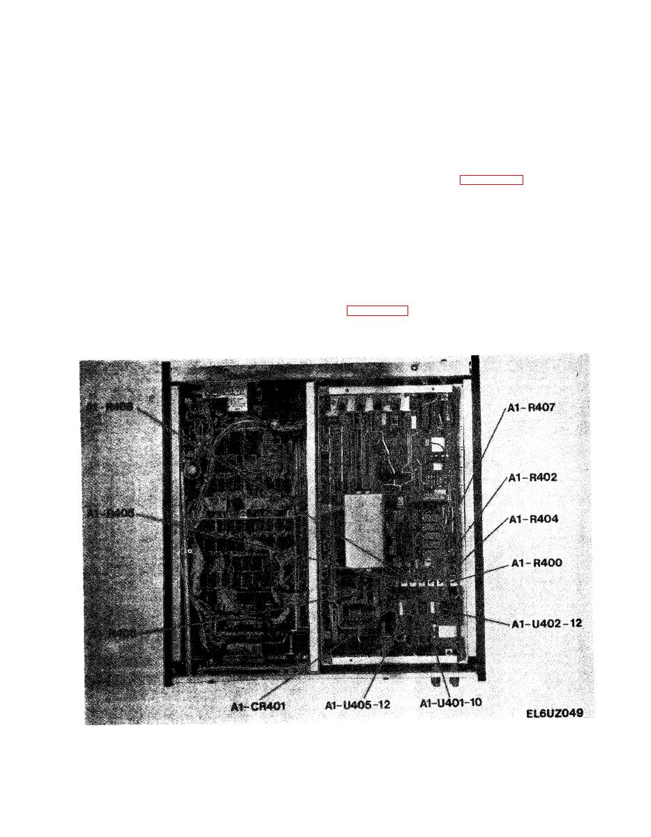
(A1-R406).
Refer to figure 6-24 for location of
U50, pin 10 just switches from +5 V to -15V (or
adjustments.
from -15 V to +5 V).
(1) R e m o v e the top Guard Cage Cover.
(5) Decrease the input signal from the dc
voltage calibrator to +111.0 Vdc. The voltage at
A9-U50, pin 10 should read +5 volts.
(2) R e m o v e the True Rms Converter Board
Assembly (A7).
(6) Increase the input signal from the dc
voltage calibrator to +113.0 volts. The voltage
(3) Connect the equipment as shown in
at A9-U50, pin 10 should read -15 volts.


