TM 11-6625-444-14-2
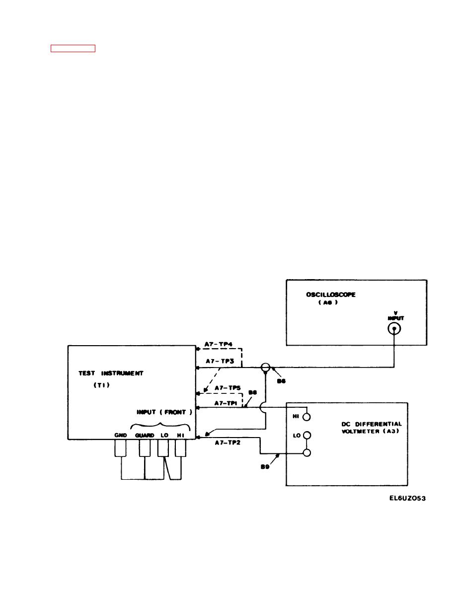
(1) Connect the equipment as shown in
(5) Select the 1 V range and .01 V NULL
sensitivity on the differential voltmeter (A3) and
s e t its dials +0.0000. This provides a meter
indication of 0.01 V full scale on the dc dif-
NOTE
ferential voltmeter and corresponds to a count of
1000 on the voltmeter. Each major division on
the dc differential voltmeter is then equivalent to
It is not necessary to connect the os-
cilloscope (A6) at this time.
100 counts on the voltmeter.
(6) If the NULL indication on the differen-
(2) Select the 2 V range and AC + DC
tial voltmeter is greater than 0.001 V (100
VOLTS function on the voltmeter. All other but-
c o u n t s ) it will be necessary to increase or
tons should be released to the "out" position.
decrease the value of either A7-R17 or A7-R25,
or both. When the reading is less than 0.001 V
proceed to step (7).
(3) Set the front panel AC NULL control to
the center of its mechanical rotation. To do this,
(7) Apply the tip of a heated 60 watt sold-
first turn the control completely clockwise until
e r i n g iron to the top of transistor A7-Q4 for
an audible click is heard. Then, rotate the con-
about 5 seconds. At the end of this time, re-
trol counterclockwise ten complete turns.
move the soldering iron and observe the magni-
tude and direction of any change in reading on
the dc differential voltmeter.
(4) Remove the Top Guard Cage Cover.


