TM 11-6625-444-14-2
the output of operational amplifier, U401B to
V. This applies a logic "high" to U403C pin 11;
swing towards the open collector supply voltage
pin 12 of U403C is already enabled because the
of +5V. This again results in a logic "low" at the
RATIO mode has been selected. The output of
p h o t o - c e l l , U407, producing a "Down Range
NAND gate U403C pin 13 is a logic "low". This
command".
"low" is applied to photocell U407, producing a
"Down Range command".
Minus Input Signal
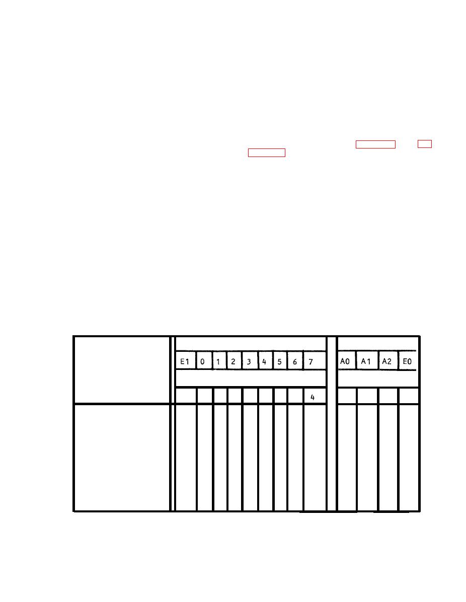
To understand the function logic, refer to the
Function Selection diagram, figure 5-2, and ta-
When a -14 V input voltage is used, the volt-
b l e s 5-8 and 5-9.
Manual inputs are applied
age at the output of U400 becomes -7 V. For
t h r o u g h front panel push button switches to
the same 100 V reference voltage, a +10 V re-
gates A2-U1 and A2-U2. These gates are en-
ference will be present at RN403-10, 11. These
abled when the output logic of A2-U57, pin 9 is
two voltages are "summed" at the junction of
"high". When this logic is "low", the remote in-
RN403-10,11 and RN403-11,12 and the result-
p u t gates, A2-U12 and A2-U13 are enabled.
ing voltage level is 0 V. This voltage is applied
Either the manual or remote input logic is direct-
to the non-inverting input of U401B (pin 6). A
ed to the function encoder, A2-U8, an eight-line
reference voltage of "0" V, set by adjustment of
to three-line priority encoder.
R402, is applied to the inverting input of U401B
I f the -14 V input signal becomes
(pin 7).
slightly less negative, then the -7 V at
The output of A2-U8 is applied through invert-
RN403-11,12 also becomes slightly less nega-
ers as a BCD input to Function Decoder,
t i v e ; the voltage at the summing point goes
A2-U251.
This input logic then selects one of
slightly more positive than 0 volts. This causes
the output lines to be "low" which determines
the output of operational amplifier, U401B to
the function selected.
Outputs
Inputs
Pin No.
Pin No.
3
Function
11 12
13
1
2
5
10
.
H
H
L
H
H
X
X
L
L
X
L
X
X
DC/DC RATIO
L
H
H
H
H
H
H
H
H
H
H
L
H
DC VOLTS
H
H
H
H
H
H
H
H
H
H
L
L
H
AC VOLTS
H
H
H
H
H
L
H
L
L
X
L
X
X
AC+DC VOLTS
i-i
H
L
L
L
H
L
X
X
X
X
X
X
FILTER (AC)
H
L
L
L
L
X
X
X
X
X
X
X
L
FILTER(AC+DC)
L = 0 V; H= +5 V; X= DON'T CARE


