TM 11-6625-444-14-2
External
V
Input
RANGE
Reference
Display (%)
Voltage
1
V
1.0
V
100.000%
2
2
V
2.0
V
100.000%
2
2
V
2.0
V
100.000%
20
10.0
V
10V
100.000%
20
100.0 V
100.000%
200
100 V
100.0 V
100V
100.000%
1000
j. Observe the display reading. It will indicate
PUT terminals, the red test lead to the HI termin-
al and the black test lead to the LO terminal.
the ratio of the input voltage to the external re-
ference voltage, up to a maximum of 19999.9%.
c. Push the AC VOLTS switch to the in po-
sition.
NOTE
d. For input signals with frequency compo-
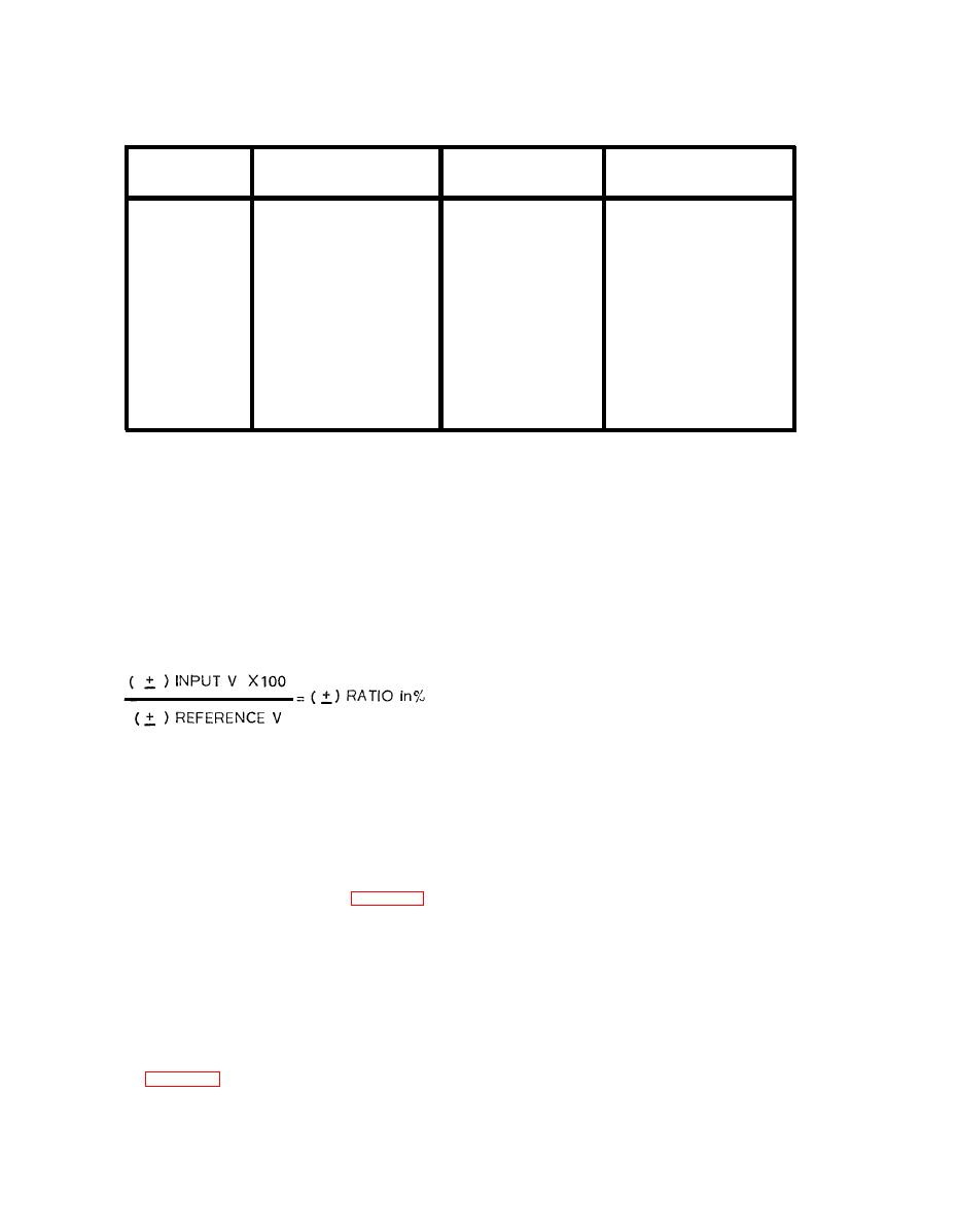
The polarity of the displayed ratio
nents higher than 10 kHz, leave the FILTER
reading is the algebraic sign of the
switch in the out position.
Push the FILTER
quotient resulting from:
switch to the LP/10 kHz position when measur-
ing low frequency signals (< 1 kHz) to insert the
10 kHz (-3 dB) low pass filter.
NOTE
For ac voltages having a frequency
lower than 40 Hz it may be neces-
sary to use the AC+DC VOLTS mode.
The voltmeter will measure true rms ac voltages
If the low frequency input signal has
from 0.0001 to 1000.00 volts on four separate
a dc component, the dc may be
ranges; 2, 20, 200 and 1000 V. Automatic rang-
blocked with a large capacitor con-
ing may be selected.
nected externally in series with the
HI INPUT binding post. Use only a
high quality polypropylene dielectric
extended foil capacitor.
NOTE
If a guarded measurement is not
e. For frequencies lower than 40 Hz, push the
necessary, leave the GUARD
SLOW RESPONSE switch to the in position.
switch in the NORM position.
For guarded measurements, push
f. Select the appropriate V RANGE if the ap-
the switch in to the EXT position.
proximate value is known; if the voltage is un-
See para 3-3.
known or its range will be extensive, select the
autoranging mode by pushing the AUTO switch
b. Connect the test leads to the HI and LO lN-
to the in position.


