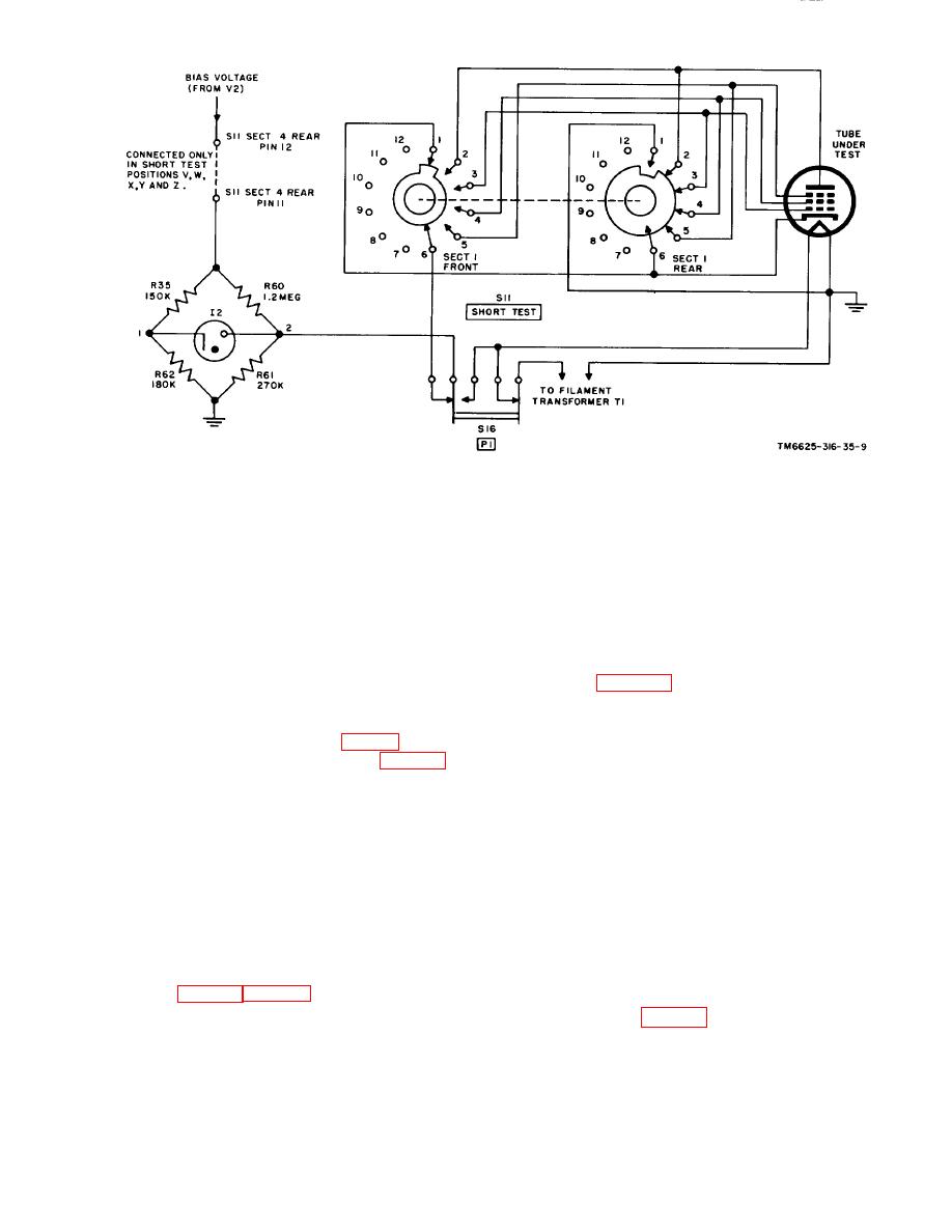
Figure 9. Short and filament continuing test circuit of Test Set, Electron Tube
TV-2(*)/U, simplified schematic diagram.
ventional ohmmeter circuit measures the inter-
10. Filament Continuity Test Circuit
element leakage resistance in a tube under test.
The filament continuity test circuit of Test
A simplified schematic diagram of this circuit
Set, Electron Tube TV-2(*)/U provides visual
is shown in figure 10. When FUNCTION switch
indication of filament continuity of hot-cathode
S4 is in the LEAK position, a portion of the
electron tubes, ballast tubes, and indicator
bias voltage from tube V2 is applied to the tube
lamps. The action of this circuit is identical with
under test through SHORT TEST switch S11
that of the short test circuit (par. 9) ; a simpli.
and PLATE meter M5. Resistor R38 is a series-
fied schematic diagram is shown in figure 9. The
multiplier for meter M5, which serves as an
operation of PRESS TO TEST PI switch S16
ohmmeter. Any element of the tube under test
connects the filament or filaments of the tube
can be selected by switch S11. If low leakage
under test across resistor R61 and removes fila-
resistance exists between the element selected
ment voltage from the tube. If the filament is
and any other element of the tube, leakage cur-
closed, its low resistance, placed in parallel with
rent completes the series circuit and meter MS
FIL. CONT. SHORT lamp 12, will increase the
indicates the equivalent leakage resistance in
voltage across lamp 12 and the lamp will light.
megohms. If there is no leakage, meter M5 will
If the filament of the tube under test is open,
not deflect; this will indicate a high resistance.
the voltage across lamp 12 is too low for the
The scale of meter M5 is not designed to indicate
lamp to light.
a very low leakage resistance of a few hundred
11. Leakage Test Circuit
ohms or less. However, such a partially short-
circuited condition can be detected by perform-
In Test Set, Electron Tube TV-2(*)/U, a con-
ing the short test (par. 9).
14
AGO 1428A


