TM6625-316-35-7
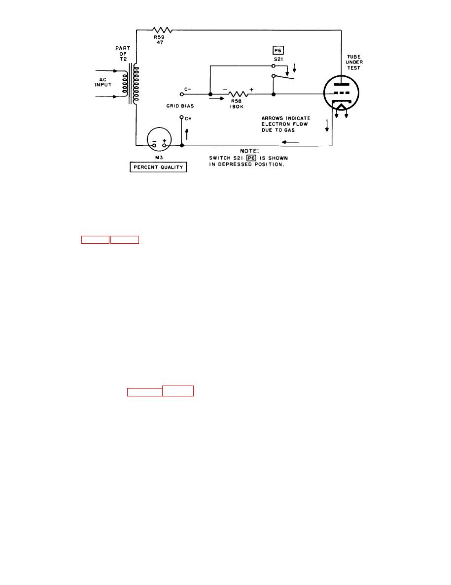
Figure 7. Gas test circuit of T e s t Set, Electron Tube TV-2(*)/U, simplified schematic
diagram
M5 when the plate voltage is either 20 or 35
8. Voltage Regulator and Thyraton
volts ac. The total amount of load current de-
Tube Test Circuit
pends on the resistance network of the meter
and the setting of potentiometer R46B. With
a. Voltage-regulator tubes, gas-filled recti-
SIGNAL-V.R. potentiometer R46B, PLATE po-
fier tubes, and thyratron tubes must have low-
tentiometer R45, and SCREEN potentiometer
voltage regulation to perform efficiently. A test
R54 adjusted for the minimum and maximum
that measures the voltage drop across a tube
load currents specified for the tube under test,
under test can be used to determine the regula-
the voltage drop across the tube is indicated on
tion of the tube under varying load conditions.
meter M3 for each load condition. Minimum
By measuring the voltage drop of the tube under
limits for the tube under test are specified in
minimum and maximum load conditions, the
the tube test data roll chart.
regulation of the tube in volts can be obtained
c. In the case of thyratron tubes and gas
by using the following equation:
triodes, a bias voltage normally is applied to the
Regulation = Emax -- Emin
grid of the tube under test which is at a suffi-
In this formula, Emax and Emin represents the
ciently negative voltage to prevent ionization of
voltage drops across the tube under maximum
the gas in the tube. As grid bias is reduced, a
and minimum load conditions.
critical voltage, called striking voltage, is reach-
b. The voltage regulator and thyratron tube
ed. At this point, the electrons emitted from the
test circuit used in Test Set, Electron Tube TV-
cathode gain sufficient energy to ionize the gas
within the tube. At the striking point, all gas in
voltage taken from bleeder resistor R55 of the
the tube is suddenly ionized and a large gas cur-
screen supply circuit is fed to the plate of the
rent, which is no longer controlled by the grid
tube under test through PRESS TO TEST P5
bias voltage, results. The important character-
switch S20 and SIGNAL-V.R. potentiometer
istic of gas triodes, therefore, is the striking
R46B. The voltage drop across the tube is meas-
voltage of the tube.
ured by PERCENT QUALITY meter M3, which
is placed in parallel with quality SHUNT poten-
d. To measure the striking voltage of gas
tiometer RX3. The load current through the tube
triodes, BIAS potentiometer R29 and BIAS
under test is indicated on PLATE meter M5.
RANGE switch S2 are adjusted until the tube
Tube V 1 is used as a meter rectifier for meter
under test strikes. This is indicated by a flow
12
AGO 1428A


