selected by PLATE-SCREEN RANGE switch
5. Transconductance Test Circuit
S3 through sections 1 and 2. Terminals 9 and 10
of transformer T2 are connected to the PER-
a. In an amplifier tube, a small change in grid
CENT QUALITY meter M3. Quality SHUNT
voltage causes a large change in plate current.
potentiometer R33, connected in parallel with
The greater the change in plate current pro-
meter M3, permits adjustment of meter sensi-
duced by a given change in the applied grid
tivity. The rear section of GM-SIGNAL RANGE
potential (ac signal), the better the perform-
switch S5 connects quality meter multiplier
ance of the tube as an amplifier if other char-
resistors R30 and R31 in series with meter M3.
acteristics remain constant. The amount of plate
The center-tapped resistance network that
current change ( p) produced by a grid volt-
consists of resistors R40 and R42 and GM CEN-
age change ( ∆ Eg) will give the measure of the
TERING potentiometer R44 are placed in par-
quality of a tube which can be used to compare
allel with meter M3. The center tap of poten-
other tubes. This quality figure of a tube is called
tiometer R44 is connected to ground and to the
mutual conductance or grid-plate transconduct-
cathode of the tube under test to maintain the
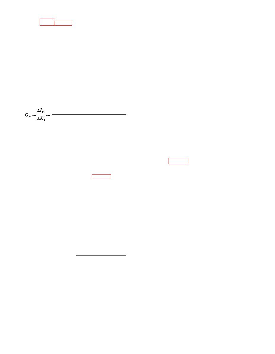
ance (Gm) and may be defined by:
proper balance of resistance in this network,
Change in plate current produced
and to adjust for zero deflection of meter M3.
(microampere) (plate voltage kept
The tube under test is the load of the rectifier
constant)
circuit. Fixed or cathode bias, as well as various
signal voltages, is applied to the grid of the tube
Change in grid voltage producing
u n d e r test through GM-SIGNAL RANGE
change in plate current (volts)
switch S5.
Mutual conductance is measured in micromhos.
The rated value of mutual conductance in mi-
d. When plate No. 1 of tube VI is at an in-
cromhos for each tube type represents the trans-
stantaneous positive potential, plate No. 2 is at
conductance at the optimum point of the tube's
an instantaneously negative potential; electron
characteristics. The characteristics of a tube,
flow is through resistor R40 and potentiometer
designated by a series of curves, are used in the
R44 to the tube under test, as indicated by the
design of electron tube circuits to get the best
solid arrows in figure 5 (press to test switch
possible performance from a tube.
S19 is open). This would cause meter M3 to
b. The quality test circuit of Test Set, Elec-
deflect in one direction. During the next half-
tron Tube TB-2(*)/U, shown in figure 5, meas-
cycle of the ac signal voltage, plate No. 1 is at
ures the mutual conductance of electron tubes.
a negative potential while plate No. 2 is at a
Because a figure of merit of the relative per-
positive potential; electron flow is through resis-
formance of a tube is more valuable than the
tor R42 and potentiometer R44 to the tube under
actual value of mutual conductance, the scale of
test, as indicated by the broken arrows. This
PERCENT QUALITY meter M3 is calibrated
would cause meter M3 to deflect in the opposite
directly in percent quality of the rated mutual
direction. Equal currents flow in the directions
conductance. The actual value of mutual con-
of both the solid and broken arrows. Because
ductance of the tube under test can be obtained
meter M3 is incapable of following the equal and
by multiplying the value indicated on the scale
opposite positive and negative deflections at the
of meter M3 by the rated value of mutual con-
power line frequency, however, the pointer re-
ductance of the tube:
mains at zero. Therefore, when the current that
Percent quality x rated
flows through resistor R40 and potentiometer
value of Gm ( m i c r o m -
R44 is exactly equal to the current that flows
hos)
through resistor R42 and potentiometer R44,
Mutual conductance
=
they will balance out and meter M3 will not de-
( Gm )
100
flect. If the currents are not exactly equal, poten-
c. The transconductance measuring circuit
tiometer R44 is used to achieve this balanced
used in Test Set, Electron Tube TV-2(*)/U con-
condition.
sists essentially of a simple full-wave rectifier
e. In addition to the dc bias voltage normally
circuit, that uses plate supply rectifier tube V1
present, an ac signal voltage is applied to the
and split plate voltage winding 3-14 of power
grid of the tube under test (press to test switch
transformer T2. Various plate voltages are
AGO 1428A
9


