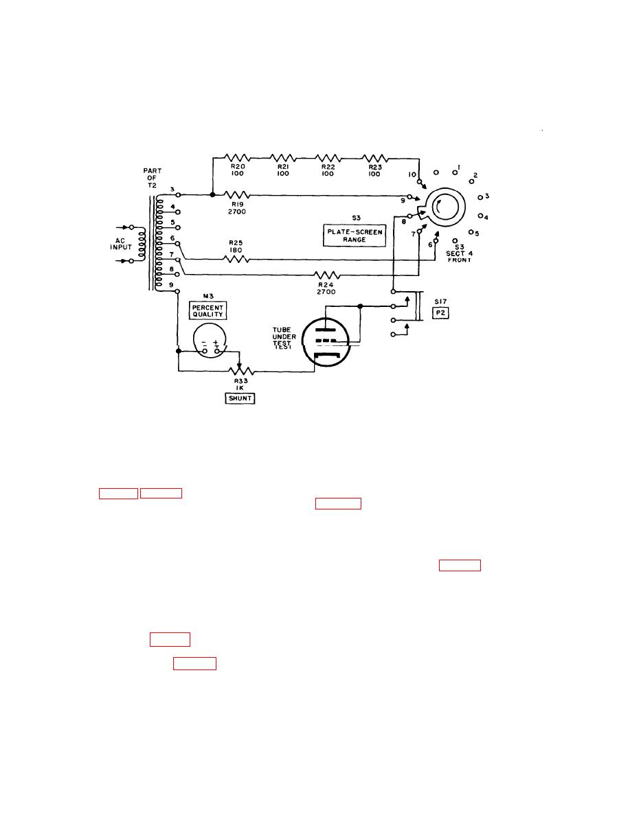
c. For diodes, depressing PRESS TO TEST
grids are connected to the plate while the sup-
P2 switch S17 applies voltage to the tube under
pressor grid is tied to the cathode; the tube them
test and emission current is read in percent
functions as a diode. When PRESS TO TEST
P3 switch S18 is depressed at the same time as
quality of the rated value on PERCENT QUAL-
ITY meter M3.
P2 switch S17, emission current is read in per-
cent quality of the rated value on PERCENT
d. For multigrid tubes, the control and screen
QUALITY meter M3.
NOTE:
ON TV-2C/U, R24 AND R25 ARE
CONNECTED DIFFERENTLY. REFER
TO SCHEMATIC DIAGRAM.
TM6625-316-35-6
Emission measurement circuit of Test Set, Electron Tube TV-2(*)/U,
Figure 6.
Simplified Schematic diagram.
which depends on the plate and grid voltages
7. Gas Test Circuit
set up for the transconductance test of the tube
a. A gas test performed' on an amplifier-type
S21 to insert resistor R58 into the grid circuit of
tube will detect an excessive amount of gas in
the tube under test. If the tube is gassy, the
the tube. A gassy tube will not function cor-
source of grid-bias voltage C will cause current
rectly. Ionization of residual gas in a tube causes
to flow through the grid circuit in the direction
grid current to flow, and thus changes the grid-
indicated by the arrows (fig. 7). The gas cur-
bias voltage and other operating characteristics
rent develops a voltage drop across resistor
of a tube.
R58, which tends to place the grid end of the
resistor at a positive potential and reduce the
negative grid bias; an increase in plate current
b. The gas test circuit of Test Set, Electron
results. This increase in plate current is indi-
Tube TV2(*)/U is part of the transconduct-
cated on PERCENT QUALITY meter M3. The
ance test circuit (par. 5) only parts involving
pointer of meter M3 will move less than three-
the grid circuit are shown in the simplified
scale divisions if the tube under test has a negli-
schematic diagram (fig. 7). Plate current
gible gas content.
through the tube under test has a certain value,
11
AGO 1428A


