TM 11-6625-2616-14
h. Jumpering. Whenever an electrical connec-
wire or clip lead, If this fixes the problem then,
tion is suspected of being faulty, it is usually
of course the connection must be repaired.
possible to parallel the connection with a jumper
Section Il. TROUBLESHOOTING DIGITAL VOLTMETER AN/GSM-64A
b. Connect the unit to a 115 vac power source
6-4. General
as required.
The foregoing has provided the organization and
general techniques of the troubleshooting pro-
c. Connect the test equipment as specified for
cess. The following paragraphs provide detailed
each particular test (para 6-8 through 6-15).
troubleshooting information which, coupled with
a thorough understanding of the functioning data
described in chapter 5, should enable the repair-
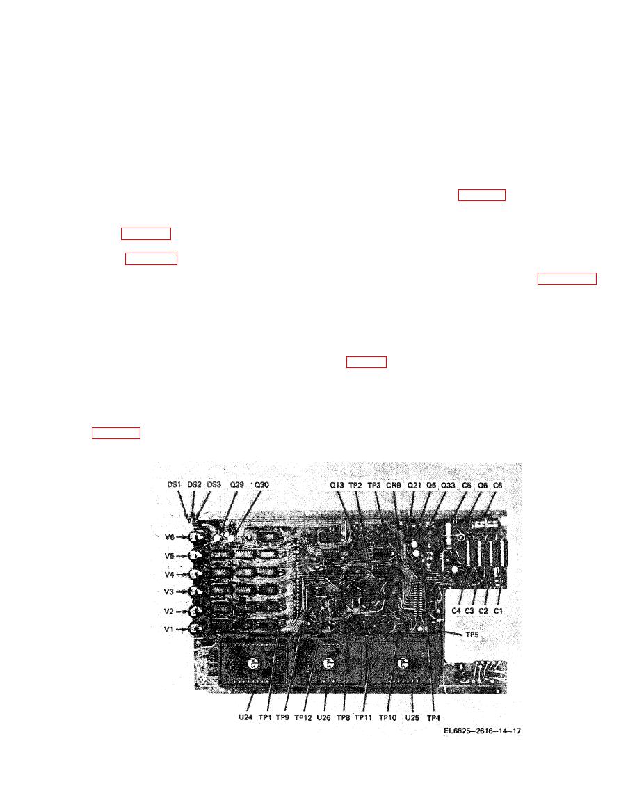
a. General. In the troubleshooting chart ( d
man to isolate the cause of the trouble and, with
below) procedures are given for localizing troubles
reference to chapter 7, to effect repair.
to a circuit or a specific component. Parts loca-
tions and test points are shown in figures 6-1
and 6-2. Integrated circuits are not called out
a. DC voltage standard, John Fluke Model
on the figures since their reference designations
332A ( FSN 66252398924), or equivalent.
are etched on the printed circuit board,
b. Resistor and Capacitor Color Code Diagrams.
Color code diagrams for resistors and capacitors
d. Variac, Superior Electric Co. Type 3PN.
capacitance, voltage rating, and tolerance infor-
mation.
c. Use of Chart. When an abnormal symptom
a. Disassemble the instrument only so far as
has been observed in the instrument, look for a
is required to perform the specified checks or
description of this symptom in the Trouble symp-
tests (para 7-2a).
Figure 6-1. Main board assembly.


