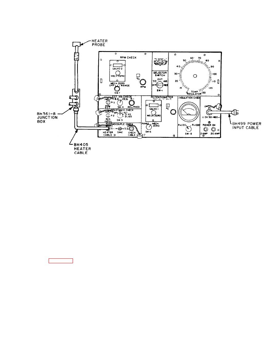
TM 55-4920-244-14
f. Place switch SW-6 in RANGE position.
that there is continuity from junction box,
through heater cable, and galvanomeer.
for deflection
g. Note galvanometers
g. Place TEMP. REGULATOR knob in 0
which indicates continuity through check cable to
position and switch SW-1 in OFF position. Dis-
galvanometers.
connect heater probe at junction box.
h. Repeat f and g above and test remain-
NOTE
ing healer probes and junction box outlets.
i. Replace any heater probe that does not
If no deflection is noted,
indicate a temperature rise on galvanometers.
make sure indication on
Replace junction box if any outlet does not indi-
o
C scale is not equal to
cate continuity.
ambient temperature.
j. Place SW-6 in MECH. ZERO position.
h. Replace check cable if galvanometers
3-14. Check Cable Circuit Continuity Check.
does not indicate continuity.
i. Place switch SW-6 in MECH. ZERO
After 10 test operations, the check cable
circuit shall be operationally checked as follows.
position.
a. Connect check cable to CHECK
j. Place switch SW-2 in SW-1 position and
CABLE connector.
remove replacement thermocouple from check
b. Insert a replacement thermocouple of
cable.
known quality in terminals A-, B+) of check
cable.
k. Remove check cable from CHECK
c. Place switch SW-1 in T/C position.
CABLE connector.
d. Place switch SW-2 in S-2 position.
l. Properly stow check cable in cable stor-
e. Place switch SW-6 in MECH. ZERO
age compartment.
position and zero galvanometers with mechanical
zero knob.
m. Secure tester after operation.


