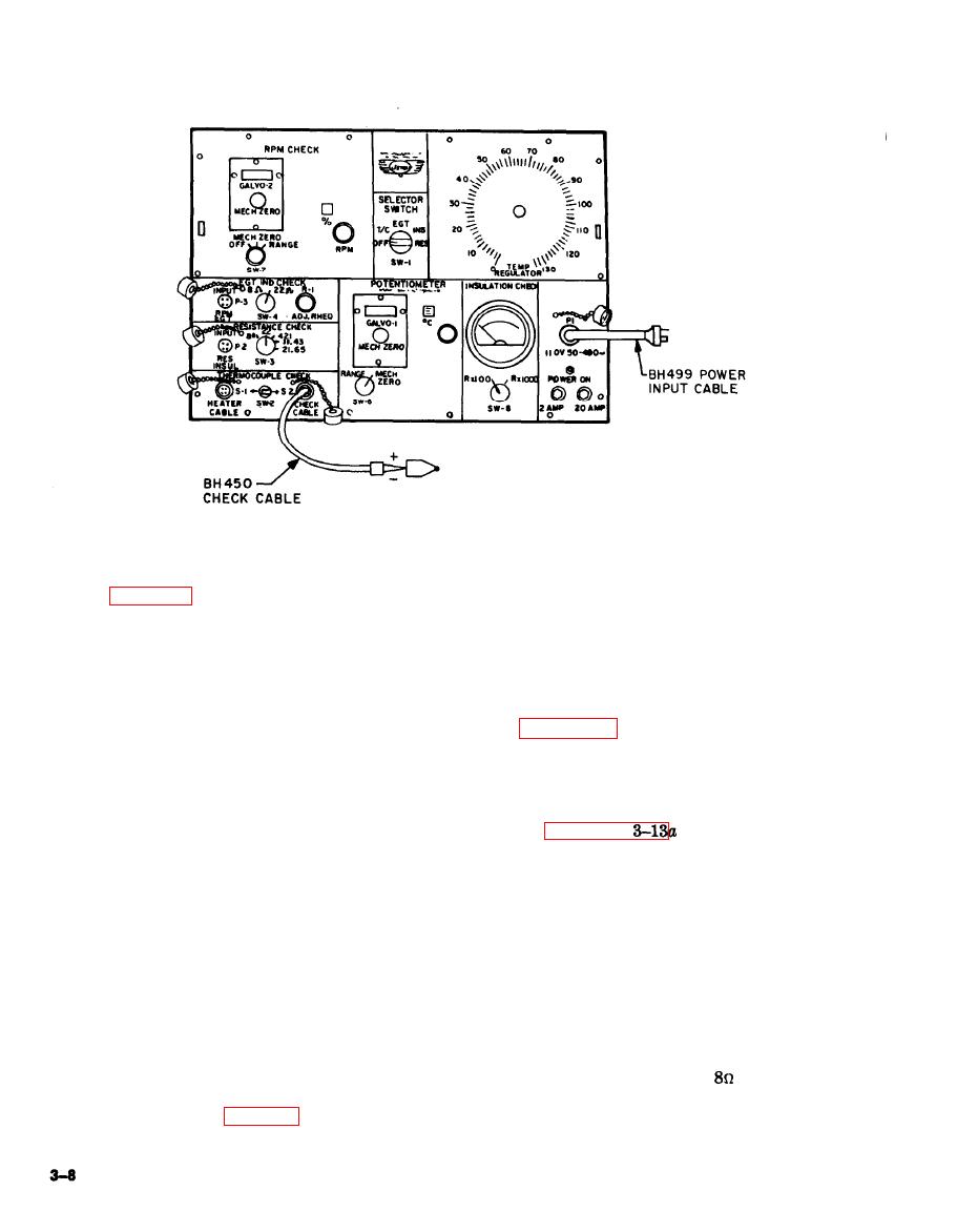
TM 55-4920-244-14
i. Place switch SW-6 in MECH. ZERO po-
3-15. Potentiometer Continuity Check.
sition.
j. Place switch SW-2 in S-1 position and
After 10 test operations, the POTENTI-
remove replacement thermocouple from CHECK
OMETER circuit shall be operationally checked
CABLE connector.
as follows:
k. Secure tester after operation.
CAUTION
3-16. EGT Indicator Circuit Operation Check.
Never use an ohmmeter or
voltmeter to check the po-
After 25 test operations, the EGT indi-
tentiometer circuit for con-
cator circuit shall be functionally checked as fol-
tinuity as damage to gal-
lows:
vanometers will result.
a. Prepare tester for operation in accord-
a. Insert a replacement thermocouple of
ance with paragraph
through c.
known quality in A (-) and B (+) sockets of
b. Connect instrument cable to egt indi-
CHECK CABLE connector.
cator check adapter and instrument cable to
b. Place switch SW-1 in T/C position.
connector P-3.
c. Place switch SW-2 in S-2 position.
c. Place switch SW-1 in EGT position.
d. Place switch SW-6 in MECH. ZERO
d. Place switch SW-6 in MECH. ZERO
position and zero galvanometers with mechanical
position and zero galvanometers with mechanical
zero knob.
zero knob.
e. Place switch SW-6 in RANGE position.
e. Place switch SW-6 in RANGE posi-
f. Apply heat to the replacement thermo-
tion.
couple.
f. Connect terminals of egt indicator check
g. With replacement thermocouple heat-
adapter together.
ing, note galvanometers for deflection which indi-
cates continuity of the potentiometer circuit.
g. Place switch SW-4 in
position.
h. If potentiometer circuit does not indi-
h. Turn potentiometer R-1 and note gal-
cate continuity, refer to Table 3-2 to locate de-
vanometers which indicates egt indicator circuit
fects.
continuity.


