TM 55-4920-244-14
CAUTION
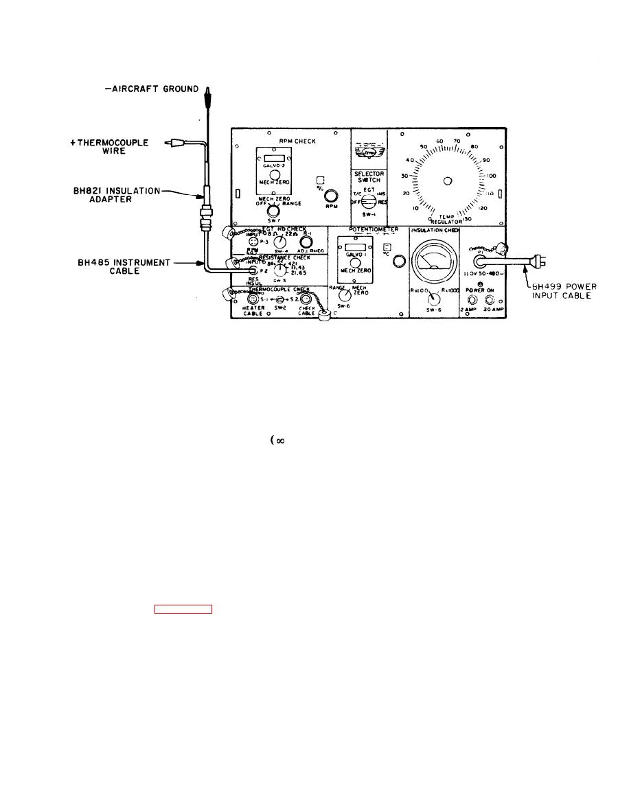
d. Place switch SW-1 in INSUL. position.
e. Place switch SW-8 in Rx1000 position.
Never
allow
continuity
f. Place insulation check adapter leads on
check probe temperature to
both thermocouple leads at aircraft EGT indi-
go above 800 Celsius (1472
cator terminals or at parallel point. Insulation
Fahrenheit).
Damage
to
check meter should read the infinite
resist-
probe could result.
ance.
g. Place switch SW-1 in OFF position.
d. Turn TEMP. REGULATOR knob to
h. Disconnect insulation check adapter
maximum and bring continuity check probe to a
from instrument cable and aircraft EGT indicator
temperature within a range of 500 to 800 Cel-
terminals.
sius (932 to 1472 Fahrenheit) as read on C
i. Disconnect instrument cable from con-
scale.
nector P-2.
e. Place switch SW-6 in MECH. ZERO
j. Properly stow instrument cable and in-
sulation check adapter in cable storage compart-
position and zero galvanometers by turning
ment.
MECH. ZERO knob.
f. Place switch SW-6 in RANGE position
Continuity Check of Thermocouple and
to take temperature readings. Adjust tempera-
Harness (Figure 2-7).
ture selector knob until galvanometers reads zero.
NOTE
Temperature reading appears on the C scale.
Indicator
must be in-
g. Check each engine thermocouple to
stalled.
eliminate any error due to one or more engine
a. Connect continuity probe to heater
thermocouples being inoperative. When using
cable.
continuity check probe, touch end of loop or
b. Connect heater cable to HEATER CA-
twisted-type thermocouple; check sampling-type
BLE connector on tester.
thermocouples by holding V-section of continuity
check probe against case of sampling-type ther-
c. Place switch SW-1 in T/C position and
switch SW-2 in S-1 position.
mocouple end. In either case, aircraft EGT indi-


