TM 55-4920-244-14
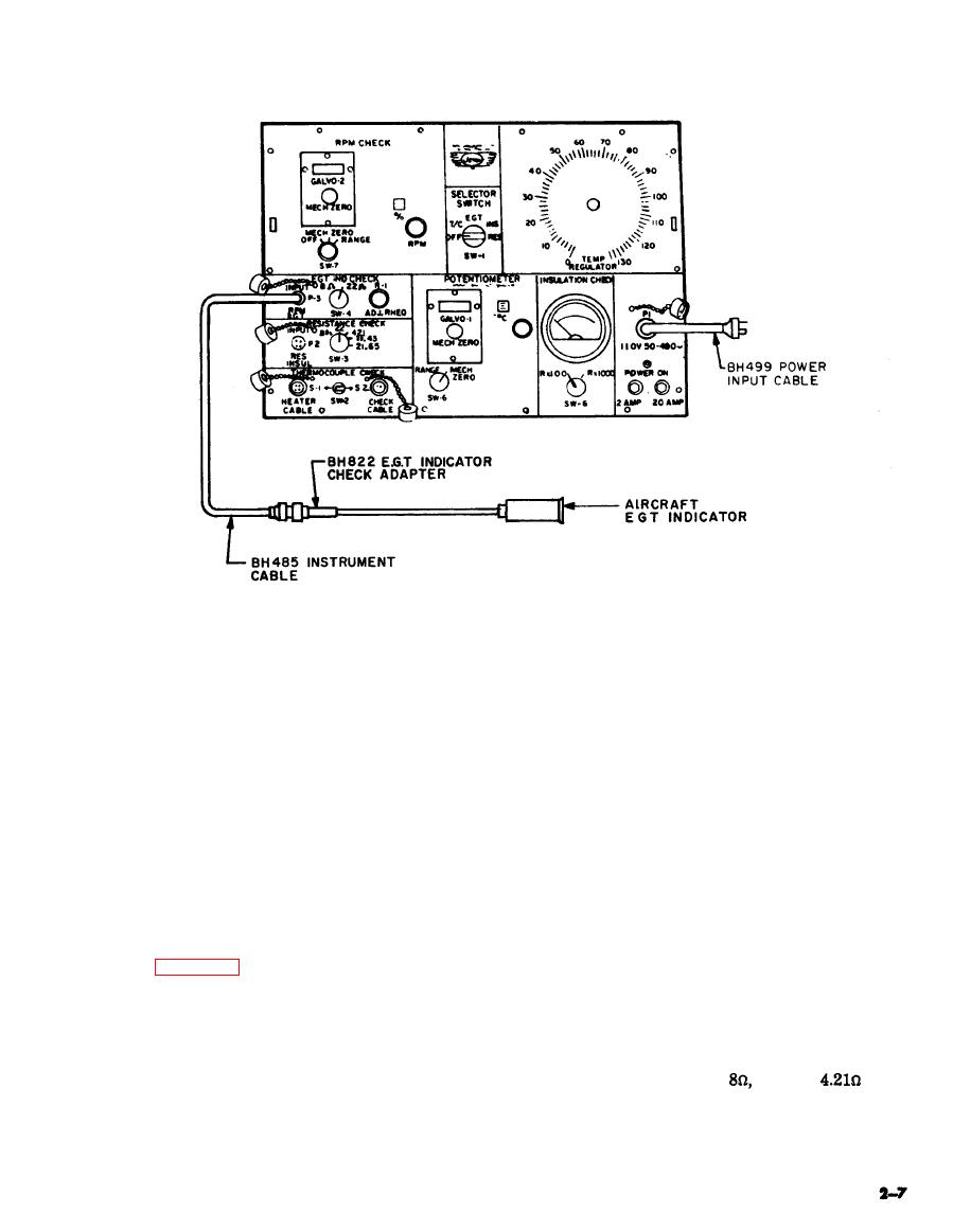
EGT indicator check.
cuit are chromel-alumel,
k. Disconnect egt indicator check adapter
resistance test s are made
from aircraft EGT indicator and instrument
with both the tester and
cable.
the aircraft at the same
l. Disconnect instrument cable from con-
ambient temperature.
nector P-3.
m. Properly stow instrument cable and
egt indicator check adapter in cable storage com-
strument cable and instrument cable to connector
partment.
P-2.
b. Disconnect thermocouple leads from
NOTE
aircraft EGT indicator.
Connect a copper wire
c. Connect resistance check adapter to
jumper across terminal
proper thermocouple leads.
posts if EGT indicator is
d. Place switch SW-6 in MECH. ZERO
not reinstalled.
position and zero galvanometers by turning
MECH. ZERO knob.
NOTE
CAUTION
Galvanometer must be
zeroed before each resist-
A high resistance condition is dangerous be-
ance check.
cause the aircraft EGT indicator will read low
and the engine will be operating above indicated
e. Turn switch SW-3 to proper aircraft
temperature.
circuit resistance (either
22w, or
posi-
tion.
NOTE
f. Place switch SW-1 in RES. position.
g. Place switch SW-6 in RANGE posi-
Since the resistors in the
tester and the aircraft cir-
tion.


