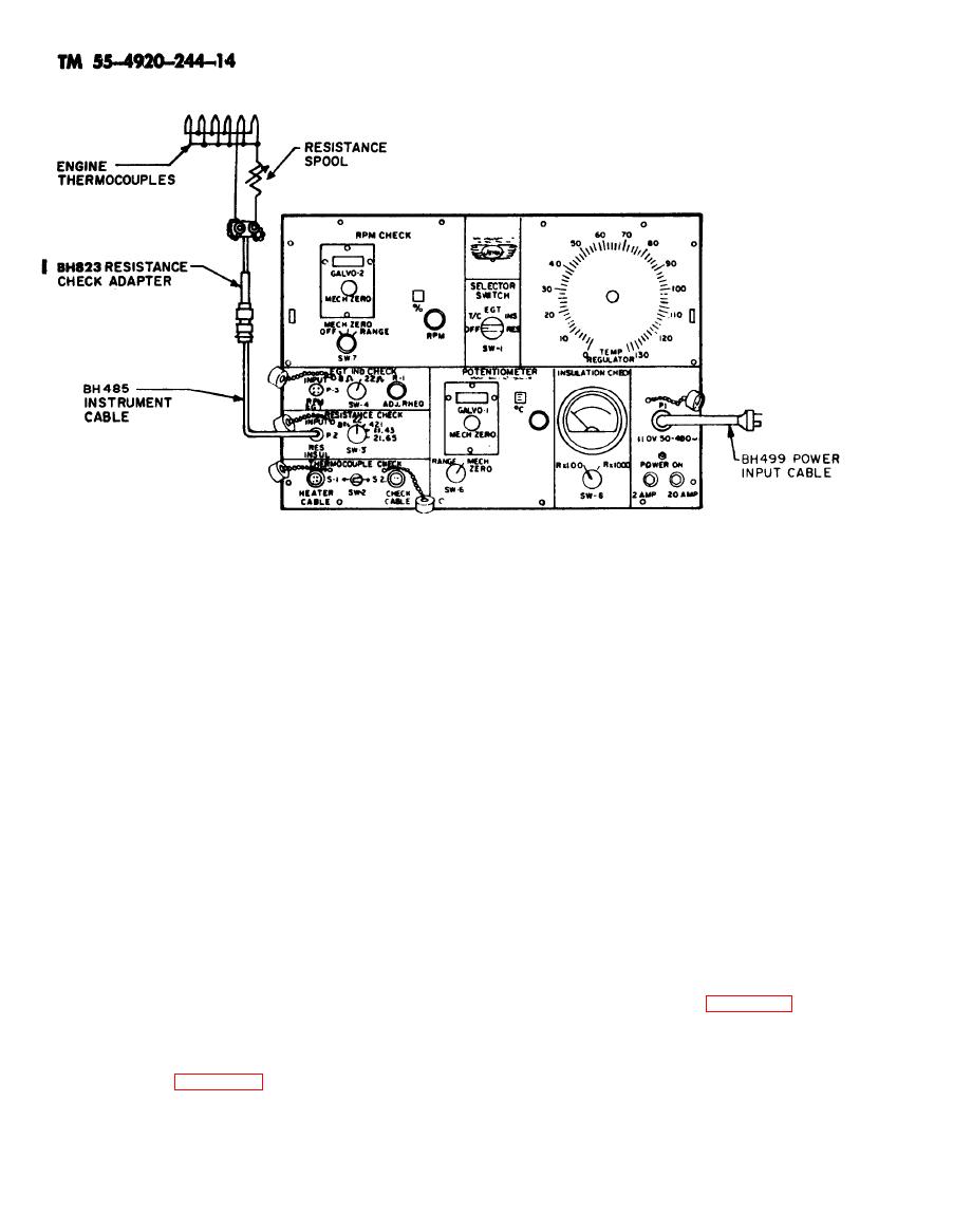
b. Place switch SW-1 in INSUL. position.
NOTE
c. Place switch SW-8 in Rx1000 position.
Clean and tighten all
d. Short insulation check adapter leads to-
thermocouple harness con-
gether. INSULATION CHECK meter should
nections before adjusting
read zero.
resistance spool.
e. Place one lead of insulation check
adapter on bare thermocouple lead in aircraft
and one lead on aircraft ground. Insulation
galvanometers reads zero plus or minus appli-
check meter should read the resistance specified
cable tolerances (one division of galvanometers
for the aircraft being checked.
equals approximately 0.05 ohm). A deflection to
f. Place switch SW-1 in OFF position.
the right indicates an increase in resistance.
g. Disconnect insulation check adapter
i. Place switch SW-6 in MECH. ZERO
from instrument cable.
position.
h. Disconnect instrument cable from con-
j. Disconnect resistance check adapter
nector P-2.
from thermocouple leads and from instrument
i. Properly stow instrument cable and in-
cable.
sulation check adapter in cable storage compart
k. Disconnect instrument cable from con-
ment.
nector P-2.
l. Properly stow instrument cable and re-
sistance check adapter in cable storage compart-
Resistance Check Circuit (Figure 2-6).
ment.
a. Remove thermocouple leads from EGT
indicator.
b. Remove thermocouple leads from en-
Ground) (Figure 2-6).
gine thermocouple harness at parallel points.
c. Connect insulation check adapter to in-
a. Connect insulation check adapter to in-
strument cable and instrument cable to connector
strument cable and instrument cable to connector
P-2.
P-2.
Change 2
2-8


