TM 55-4920-244-14
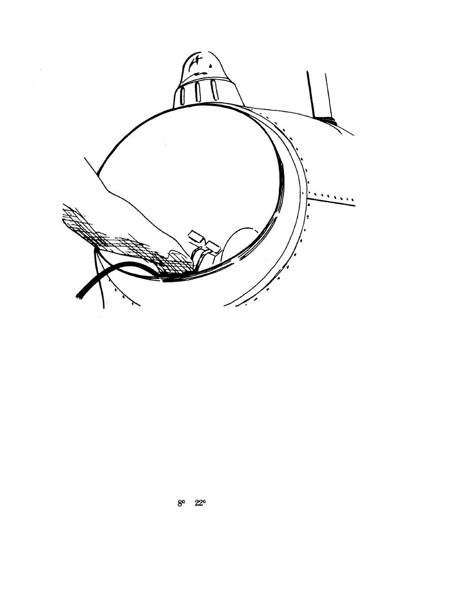
Figure 2-3. Installation of Heater Probes in Engine (Sheet 2 of 2)
h. Place switch SW-6 in RANGE position.
c. Connect egt indicator check adapter to proper ter-
minal posts on aircraft EGT indicator, observing correct
i. Turn potentiometer R-1 until galvanometers reads
polarity.
zero.
d. Place switch SW-1 in E.G.T. position
NOTE
e. Place switch SW-6 in MECH. ZERO position and
The difference between temperature
zero galvanometers by turning MECH. ZERO knob.
readings of C scale and aircraft EGT
indicator is error of aircraft EGT in-
f. Set C scale to indicate test temperature.
dicator and should not exceed ap-
plicable aircraft/engine technical
manual tolerance.
g. Turn switch SW-4 aircraft circuit resistance match-
ing aircraft EGT indicator being tested (either or
j. Place switch SW-6 in MECH. ZERO position.
position).
Change 3


