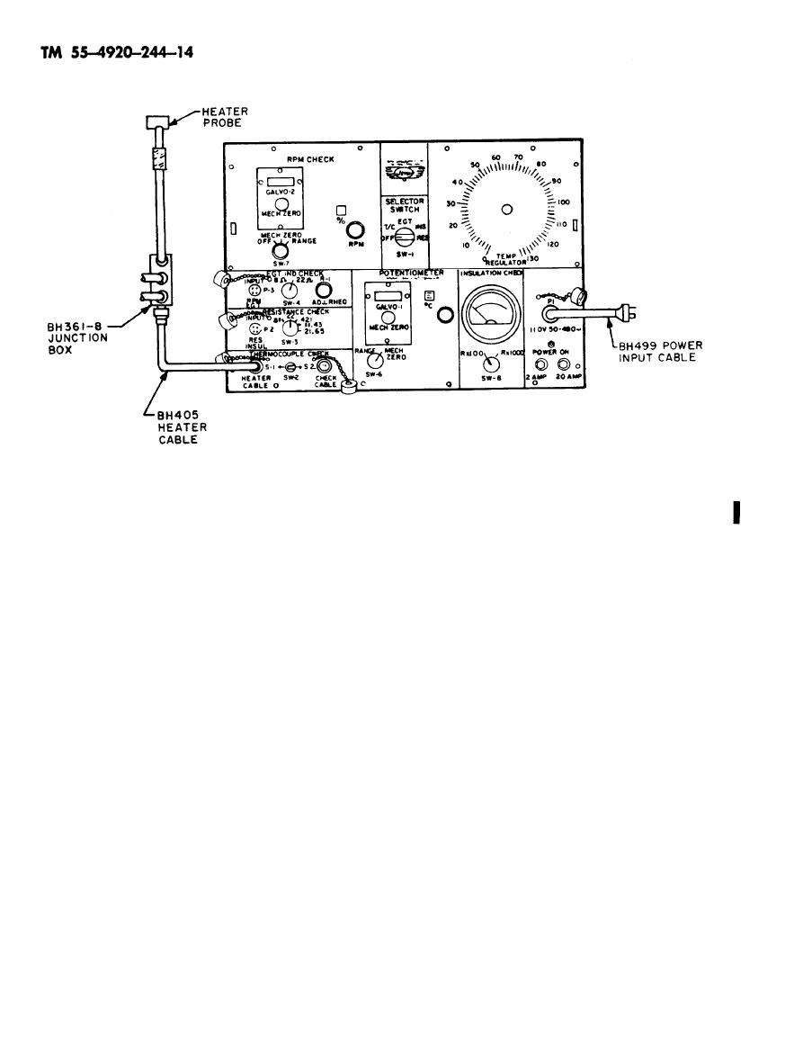
(4) Continue TEMP. REGULATOR
c. Place switch SW-6 in RANGE position.
knob adjustments until heater probes are
d. Perform temperature adjustments as
stabilized at test temperature.
outlined below.
NOTE
NOTE
If testing in high wind or
The following procedure
cold weather, it is advisa-
will aid the operator in
ble to place a cover over
making rapid adjustment
tail cone to reduce heat
of the temperature of the
dissipation. A tail cone
heater probes and tester
cover should always be
readings.
temperature
used when testing engines
With practice the oper-
equipped with sampling-
ator will be capable of
type thermocouples to
making rapid adjustments
maintain true temperature
of the heater probes.
over the entire length of
TEMP. REGULATOR
(1) Turn
thermocouple.
knob to maximum and allow heater probes to
heat to test temperature.
(5) With heater probes stabilized at
engine test temperature, read C scale and air-
(2) Adjust TEMP. REGULATOR
craft EGT indicator. Difference between these
knob back to allow temperature of heater probes
readings is indicated error of egt system and
to stabilize at test temperature (approximately 96
should not exceed applicable aircraft/engine
to 108 volts for 700 Celsius). Observe galva-
technical manual tolerance.
nometers for deflection and TEMP. REGULATOR
knob for voltage setting.
(6) Place switch SW-6 in MECH.
TEMP.
REULATOR
(3) Turn
ZERO position.
knob well above or below voltage setting, ac-
(7) Return TEMP. REGULATOR
cording to galvanometers deflection, for a few
knob to zero.
seconds.
2-4 Change 4


