TM 11-6625-539-15-2
CIRCUIT FUNCTIONING
5-1. Introduction
Circuits for Test Set, Transistor TS-1836B/U can be
divided into four functional loops: Multivibrator,
current limiting, audio amplifier, and switching. The
multivibrator stage produces an amplified square
wave signal that is applied to the switching circuits
through coupling transformer T1. The current limit-
ing network is provided for the protection of the
semiconductor under test and to limit the current to
the transistor when resistance tests are conducted.
The audio amplifier is used in conjunction with the
F.E.T. test to provide a parallel source to operate the
meter. The switching circuit incorporates a 12-posi-
tion, 9-wafer function and a 3-position, 12-pole 3-
wafer type polarity (FND PNP/OFF/REV NPN)
switch.
5-2. Battery Check
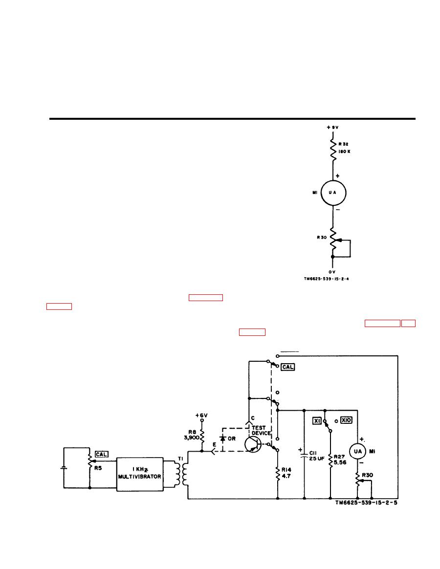
A simplified schematic diagram of the circuit used to
check the batteries in the test set is shown in figure
+9 volts is fed through series resistor R32 and meter
a. A simplified schematic diagram of the circuit
M1. The resistance of R32 limits the deflection of
used to calibrate for beta is shown in figure 5-2. Fig-
meter M1 to the BAT position on the scale.


