TM 11-6625-539-15-2
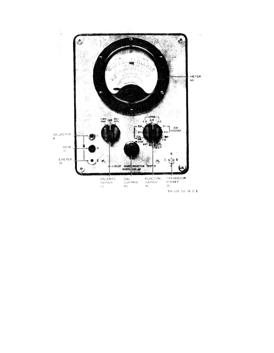
Figure 3-1. Test Set, Transistor TS-1836B/U, controls and indicators.
(BETA) scale of the meter. If the BETA falls in
c. Beta Measurement (In Circuit).
the high portion of the BETA scale, advance the
(1) Insert the three test leads supplied with the
function switch to the BETA X10 range and multi-
instrument into the three color-coded jacks on the
ply the BETA reading by 10.
front panel, being careful to insert the red probe into
the red jack, the black probe into the black jack, and
d. Electrode Resistance Measurement (In- or Out-
the yellow probe into the yellow jack. Connect the
of-Circuit).
other ends of the test leads to the transistor under
(1) Connect the leads to the transistor under
test. Be careful to connect the red-coded alligator
test, as described in b(1) above for out-of-circuit
clip to the collector, the black-coded alligator clip to
measurement, as described in c(1) above for in-cir-
the base, and the yellow-coded alligator clip to the
cuit measurement.
emitter.
(2) Place the polarity switch to correspond to
(2) Set the polarity switch to correspond to the
the type of semiconductor device being tested.
type of device being tested.
(3) Set the function switch to OHMS E-B.
(3) Set the function switch to the BETA CAL
(4) Read the resistance of the emitter-to-base
position, and adjust the CAL control for full-scale
circuitry directly on the center (OHMS) scale.
meter deflection.
(5) Set the function switch to OHMS C-B.
(4) Advance the function switch to the BETA
(6) Read the resistance of the collector-to-base
X1 range, and read the BETA directly on the top
circuitry directly on the center (OHMS) scale.
3-2


