TM 11-6625-444-14-1
INPUT terminals and connect the test equipment
(3) Connect the voltmeter power cord to a
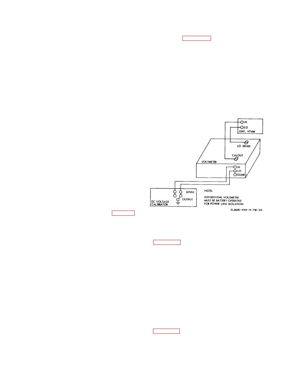
as shown in figure 6-26.
115 VAC powerline.
(2) On the differential voltmeter, set the
(4) Turn on the voltmeter and allow 30
range to one volt, the readout to .550000, and the
minutes for equipment warm up.
null sense to 0.1.
NOTE
(3) On the voltmeter, select the VDC and
Unless otherwise specified, verify the
FILT functions, select the 10 range, and turn the
results of each test and take corrective
SAM PLE RATE fully clockwise.
action whenever the test requirement is
(4) Set the dc voltage calibrator to an output
not met before proceeding.
of 0.0052 VDC.
C . Buffer Zero Adjustment. Perform buffer
(5) Adjust the A-to-D ZERO adjustment
zero adjustment as follows:
(A9R37) to obtain a digital display of +0.0005 on
(1) Select the VDC and FILT functions on
the voltmeter, and a null on the differential
the voltmeter.
voltmeter.
(2) Connect a shorting jumper between the
HI and LO INPUT terminals.
(3) Remove the top dust cover and the guard
cover.
CAUTION
If the differential voltmeter is not bat-
tery-operated, connect to the powerline
by means of an isolation transformer to
provide ac isolation between the units.
(4) Connect a differential voltmeter between
A10TP4 (LO) and A10TP3 (HI).
(5) Adjust the front panel ZERO control on
the voltmeter for a reading of 10 v on the
differential voltmeter.
d. Bias Current Adjustment. Perform bias
current adjsutment as follows:
( 1 ) Remove the shorting jumper from
between the HI and LO INPUT terminals and
replace with a one-megohm 5% resistor connected
in parallel with a 0.22f capacitor (table 6-7).
(2) Adjust the BIAS ADJ control (A11R17)
located on the buffer assembly (All) to obtain a
g. Positive Alignment Adjustment. P e r f o r m
reading between 10 V on the differential
.
the positive alignment adjustment as follows:
voltmeter.
(1) Connect the equipment as shown in
(3) Repeat steps (2), (3), and (4) of the
preceding Buffer Zero Adjustment, and repeat
(2) On the differential voltmeter, set the
step (2) of this Bias Current Adjustment until
range to one volt, the readout to .550000, and the
redings of 10 v (or better) are obtained on the
null sense to 0.1.
differential voltmeter.
(3) Turn the COMPARATOR LEVEL
e. Reference Voltage Adjustment. P e r f o r m
a d j u s t m e n t (A9R61) to the fully clockwise
reference voltage adjustment as follows:
position.
(1) Connect the differential voltmeter to the
(4) Set the dc voltage calibrator output
L O SENSE (A9TP7) and the HI SENSE
+8.00052 VDC.
(A9TP5).
(5) Adjust the +CAL adjustment (A9R17)
(2) Connect a shorting jumper between the
to obtain a digital readout of +8.0005 on the
HI and LO INPUT terminals.
voltmeter display, and a null on the differential
(3) Adjust the REF adjustment (8R57) to
voltmeter.
obtain a reading between 6.999975 and 7.000025
h . Ladder Calibration. P e r f o r m l a d d e r
on the differential voltmeter.
calibration as follows:
f. A-to-D Zero Adjustment. Perform the A-to-
(1) Connect the equipment as shown in
D zero adjustment as follows:
(1) Remove the shorting jumper from the
(2) Using the dc voltage calibrator, apply


