TM 11-6625-444-14-1
e. Turn off the voltmeter and remove the buffer
assembly (A11).
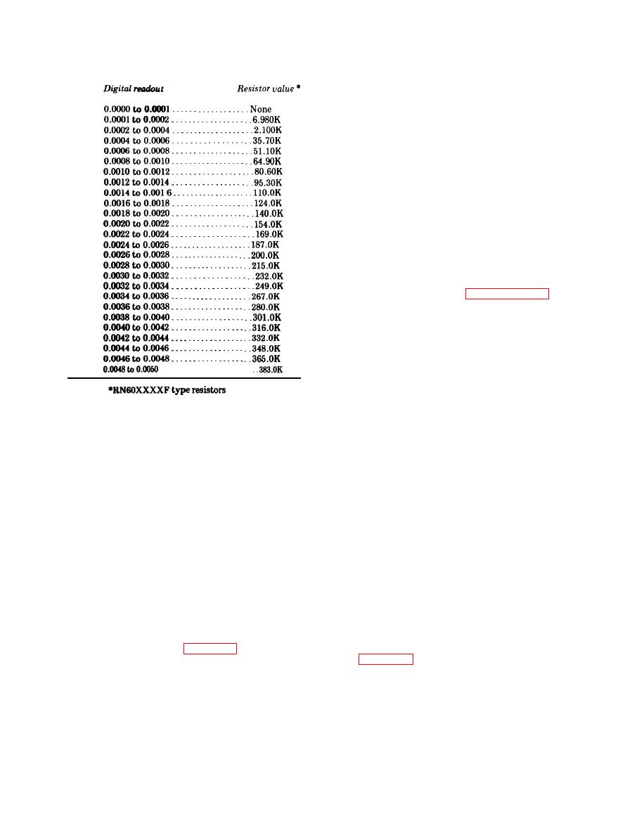
f. Install the resistor selected in accordance
with step das R22 or R25 in the buffer assembly
(A11).
position of R22 or R25.
h. Disconnect the shorting jumper across R28.
i. Install the buffer assembly (A11) in the
FILT, and 10V range are selected.
k. Adjust A11R28 (COARSE DC ZERO) for a
digital readout of 0.0000.
l. Disconnect the shorting jumper from the
INPUT terminals.
NOTE
The voltmeter requires total recalibration
in accordance with paragraph 6-16 after
selection of R22 or R25.
.................
Section IV. TESTING PROCEDURES
6-15. General
meter to ac line power and set the controls as
follows:
a. This section contains performance testing
POWER . . . . . . . . . . . . . . . . . . . . . . . . . ON
and alignment procedures for the voltmeter.
FUNCTION. . . . . . . . . . . . . . . . . . . . . VDC, FILT
Performance testing shall be conducted prior to
RANGE . . . . . . . . . . . . . . . . . . . . . . . . .10
p e r f o r m i n g any maintenance or alignment.
SAMPLE RATE . . . . . . . . . . . . . . . . . Full cw
Alignment of the voltmeter is required after any
DC ZERO . . . . . . . . . . . . . . . . . . . . . . . Midrange
RATIO FULL SCALE Midrange
maintenance affecting alignment accuracy is
performed or if unsatisfactory results are ob-
b. DC Volts Accuracy Checks.
tained from performance testing. Alignment,
(1) Connect a shorting jumper between the
however, should only be attempted if the volt
INPUT terminals.
meter is out of alignment but is fully operational
(2) Adjust the front panel DC ZERO control
b. All testing shall be conducted in a clean
for a digital readout of 00.0000 .0001.
d r a f t free environment having an ambient
(3) Connect a dc voltage calibrator to the
temperature of 730 90 F. and a relative
INPUT terminals, observing polarity.
h u m i d i t y of less than 70%. Required test
(4) Apply each of the input voltages shown
equipment is listed in table 6-7.
in table 6-11 to the INPUT terminals. The digital
readout shall be as specified.
a. Preliminary Operation. Connect the volt-


