TM 11-6625-444-14-1
100 milliseconds maximum3
2
Input volt x Hertz, product should not exceed 2 x 10⁷.
Filterout
500 milliseconds maximum.
3
Filter in
Above 400 Hz for rated accuracies.
1
With inputs above 500 volts, multiply accuracy by
Section II. OPERATION OF PL-1370 / GSM-64B
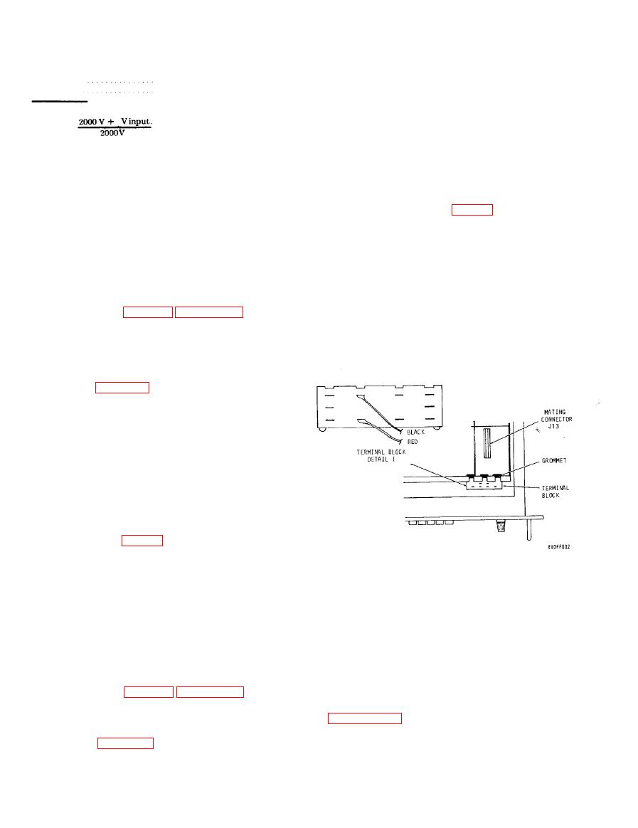
Refer to termainal block (I, fig. 7-1) for connection
points.
The ac converter kit contains a new guard cover
(5) Withdraw the cable assembly from the ac
for the voltmeter and the ac converter plug-in
converter assembly from the rubber grommet
assembly. Installation and removal instructions are
above the front card guide.
given in a and b below, respectively.
(6) Remove the ac converter assembly from
a. Installation.
the voltmeter by pulling the circuit card straight
(1) Be sure that the voltmeter is disconnected
up.
from the power source.
(7) Install the guard cover which was retained
(2) Refer to figure 2, Appendix B. Remove
when the ac converter was installed into the
top cover (2) and guard cover (10) from voltmeter,
Retain guard cover so that the voltmeter can be
(8) Reinstall the top cover.
restored to its original configuration should it be
necessary to turn-in the voltmeter and retain the
ac converter.
(3) Use figure 7-1 as a guide and locate the ac
converter assembly position in the voltmeter.
(4) Align the ac converter assembly with the
card guides at front and rear card bulkheads. Plug
the ac converter assembly into mating connector
J13. Make sure that the board edge connector and
mating connector are fully engaged.
(5) Route the cable assembly from the ac
converter assembly through the rubber grommet
above the front card guide.
(6) Attach red and black wires to terminals of
grey terminal block at front bulkhead. Refer to
terminal block (I, fig. 7-1) for connecting points.
(7) Install the replacement guard cover. Set
the input coupling switch, which can be reached
Figure 7-1. Ac converter, location diagram.
through the guard cover, to ac or dc.
7-6. Precautions and Operator's Controls
(8) Reinstall the top cover.
The ac converter is fully protected from overloads
(9) The voltmeter can now be used to make
true rms voltage measurements.
applied to the INPUT terminals of the voltmeter.
b. Removal. If it is necessary to remove the ac
The ac converter can withstand overloads up to
converter assembly prior to turn-in of the volt-
1,100 vrms (1,500 volts peak ac) on any range.
meter for any reason, proceed as follows:
When operated with ac coupling, maximum dc
(1) Disconnect the voltmeter from the power
input is 1,100 volts on any range. Peak ac plus dc
source.
must not exceed 1,500 volts. Controls used for
(2) Refer to figure 2, Appendix B. Remove
rms voltage measurements are the VAC push-
top cover cover (2) and guard cover (10) from the
button and all RANGE pushbuttons as described
voltmeter. Retain the guard cover for future use
in paragraph 3-4. The only control unique to the ac
with the ac converter assembly.
converter is the input coupling switch which can be
(3) Use figure 7-1 as a guide to locate the ac
reached through the guard cover. This control is
converter assembly position in the voltmeter.
used to select either ac coupling (blocks
(4) Disconnect red and black wires from
superimposed dc) or dc coupling (passes composite
terminals of grey terminal block at front bulkhead.
ac + dc signals).
Change 1


