TM 11-6625-444-14-1
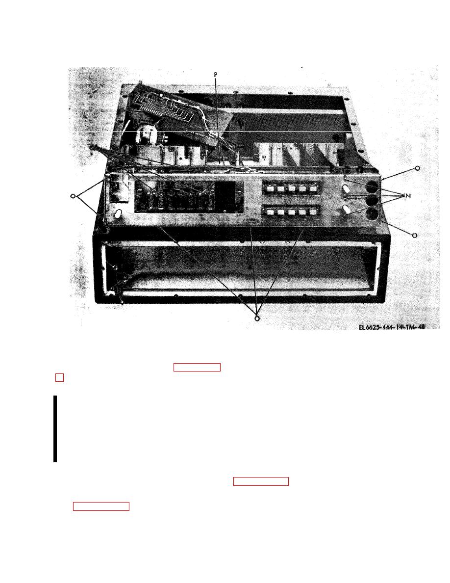
screws are accessible from the bottom of the
6-11. Cleaning
For cleaning instructions, refer to paragraph 4-
(3) Remove the plexiglass cover from the
function display by removing attaching screws.
6-12. Repair and Replacement
(4) Remove and replace the defective lamp or
NOTE
lamps using standard soldering practices.
S o l d e r i n g o p e r a t i o n s s h a l l be ac-
(5) Install the plexiglass cover and attach
complished in accordance with MIL-
using the screws removed in step (3).
HDBK- 4 5 4 A . A v ac u u m o p e r a t e d
(6) Install the function display in the volt-
resoldering tool shall also be used
meter and attach using the screws removed in step
whenever resoldering is required.
(2).
Maximum allowable soldering iron
b. Readout Tubes. Repair of the readout tubes is
wattage rating is 25 watts.
limited to replacement. Proceed as follows:
a. Function Display. Repair of the function
(1) Remove the top and bottom dust covers
display is limited to replacement of lamps
and inner guard covers in accordance with
using the following procedure.
(1) Remove the top and bottom dust
(2) Remove and replace readout tubes V 1
covers and inner guard covers in accordance
through V7 using standard soldering practices.
with paragraph 6-10a.
c. Pushbutton Switches. Repair of the push-
(2) Remove the function display located
button s w i t c h e s is l i m i t e d to r e p l a c e m e n t .
adjacent to the readout tubes near the front
Proceed as follows:
panel by removing its attaching screws. These
(1) Remove the top and bottom dust c o v e r s
Change 2


