TM 11-6625-441-12
switch to INTER; the output meter should indi-
e. Adjust the output meter for 150 ohms
cate 110 +48 mW.
s. Set interphone control transmit-interphone
f. Place the interphone test set KEYING switch
selector switch to INT, and RECEIVERS INT
in the RADIO position and hold; check to see that
switch to OFF (down position).
the KEY ON lamp lights. The output meter will
t. If testing of transmit circuits is not required,
indicate 18 to 71 milliwatts (mW).
perform the stopping procedure (para 3-6).
g. Release the KEYING switch.
h. Rotate the interphone test set TRANSMIT-
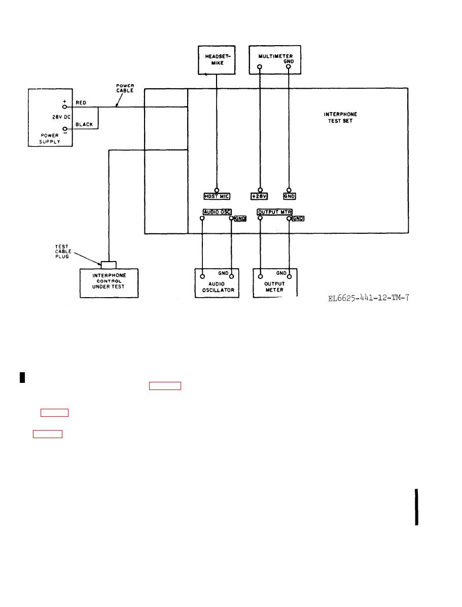
3-4. Testing Transmit Circuits
TER SEL switch and the interphone control
(figs. 3-1 and 3-2)
transmit-interphone selector switches in unison to
positions 2, 3, and 4. At each position, hold the
a. Perform the preliminary starting procedure
KEYING switch to the RADIO position. Check to
see that the KEY ON lamp lights and the output
b. Set the interphone test set controls to the
meter indicates 18 to 71 milliwatts.
following positions:
i. Rotate the interphone test set OUTPUT SEL
(1) OUTPUT SEL switch to T.
switch to I and hold the KEYING switch in the
(2) INPUT SEL switch to T.
INTER position. The output meter should indicate
(3) RECEIVER SEL switch to OFF.
18 to 71 mW.
(4) TRANSMITTER SEL switch to 1.
j. Set the interphone control transmit-
c. Set the controls of the interphone control to
interphone selector switch to INT. and hold the
the following positions:
KEYING switch in the RADIO position. The
(1) VOL control to midposition.
output meter should indicate 18-71 mw.
(2) RECEIVERS switches to OFF (down).
k. Rotate the interphone test set OUTPUT SEL
(3) Transmit-interphone selector to 1.
switch to R.
l. Rotate the interphone test set RECEIVER
output .


