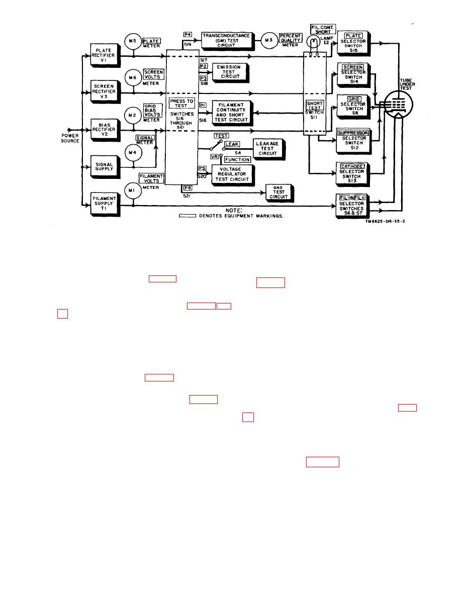
Figure 2.
Test
Electron Tube TV-2(*)/U, block diagram.
Set,
4. Power Supply Circuits
R6, R7, R8, and R9 places the filament and cath-
ode of the tube under test to the same dc potential.
c. Power Transformer T2. Power transformer
filament transformer T1 (fig. 3) is fed through
T2 (fig. 4) has six secondary windings: wind-
p o w e r switch S9, line fuses F1 and F2, and
ing 3-14, split between terminals 9 and 10 for
F I L A M E N T rheostat R1. Input power for the
the plate supply rectifier; winding 15-25 for the
screen supply rectifier; winding 2628 for the
bias supply rectifier; two filament windings, 33-
F1 and F2, and PLATE potentiometer R45. R1
35 and 3132, to heat the filaments of the 83
and R45 are used to adjust actual filament and
rectifier tube V1 and the 6X4 or 6X4W rectifier
p l a t e voltages, respectively, to the reference
tubes V2 and V3 respectively, and signal supply
value given in the tube test data roll chart. Re-
winding 29-30 to provide ac signal voltage to
sistor R18 limits the amount of current to indi-
the grid of the tube under test. PLATE-SCREEN
cator lamp 11 and resistor R2 is the filament
RANGE switch S3 is used to select the required
primary shunt resistor (fig. 3).
voltage range by selecting various taps or com-
binations of taps on the plate and screen wind-
ings up to a maximum of 250 volts dc.
ing 322 of filament transformer T1 (fig. 3) has
20 terminals nominally rated to 117 volts ac with
the use of terminal 22 as the reference. Any one
of these voltages can be selected and fed to the
nected in a full-wave rectifier circuit. Winding
3-14 of transformer T2, which feeds the plates
tube under test by setting FILAMENT RANGE
o f tube Vl, is split into two parts to permit
switch S1 to the position corresponding to the
desired filament voltage. The voltage selected is
proper interconnection of the transconductance
i n d i c a t e d on FILAMENT VOLTS meter Ml.
(G,,,) test circuit (par. 5). The dc output volt-
T h e proper FILAMENT VOLTS meter multi-
a g e for the plate of tube under test is taken
from center tap 34 of the 5-volt filament wind-
pliers, resistors R65, R3, R4, R5, and R64, are
ing 33-35 of transformer T2. PLATE meter M5
c o n n e c t e d into the meter circuit through the
indicates the dc output voltage.
rear of section 1 of switch S1. Resistor network
6
AGO 1428A


