TM 11-6625-298-14
connect the ohmmeter terminals to the moving coil
resultant of the two opposing forces that move the
assembly. The position at which the pointer finally
coil assembly.
comes to rest on the scale is determined by the
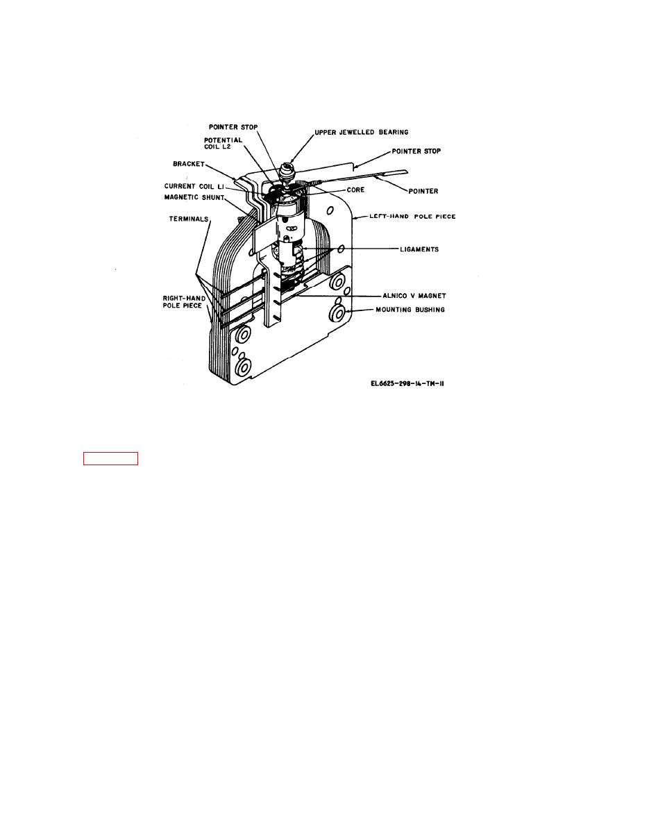
Figure 5-5. Meter assembly,
Ohmmeter ZM-21B/U.
b. An unknown resistor connected between the
line terminal and the ground terminal provide a
a. The working circuit of the insulation
another path for current flow. This path is from
resistance measuring set is designated in heavy
negative () terminal of generator G 1, through
lines in figure 5-6. The crank of the hand generator
current coil L1 of the meter, resistor R1, the line
operated at a speed of 160 rpm rotates generator
terminal, and the ground terminal to the positive
G1 at approximately 6,000 rpm. The generator
(+) side of generator G1 through the controller.
output voltage is limited to 525 volts dc by the
The magnetic field set up by current coil L1 tends
controller. With no connections made to the ohm-
to move the coil assembly and the pointer in a
meter terminals, current flows from the negative
clockwise direction. If the unknown resistance is
() terminal of generator G1, through potential
low, most of the current flows through coil L1 and
coil L2 of the meter, and through the resistors R2
and R3 (through the controller) to the positive (+)
the pointer indicates a reading close to zero. If the
value of the resistance is high, less current flows
terminal of the generator. The magnetic field set
up by potential coil L2 reacts with the field set up
through coil L1 and the pointer moves from the
zero end of the scale to indicate a point nearer
by the permanent magnet in such a way that the
coil assembly and the pointer move in a coun-
infinity.
terclockwise direction until the pointer indicates
infinity.


