TM 11-6625-298-14
FUNCTIONING OF EQUIPMENT
5-1. Function
tween two carbon brushes. When the armature is
rotated in the magnetic field, an armature voltage
is generated that is led out to the ohmmeter
insulation resistance of all types of electrical
terminals through the carbon brushes. With the
equipment and wiring. The resistance across the
generator rotating at the proper speed, the
input terminals is in series with the generator lead
predominant ripple frequency is approximately
to the meter, thus affecting the current flow
1,200 hertz (Hz) with a peak-to-peak ripple voltage
through the meter. A hand crank on the ohmmeter
of approximately 6 volts. Because of the low ac
drives the dc generator with voltage being
component, no capacitor is required across the
maintained at a constant level by an electronic
output of the generator.
controller circuit. The resistance range of the ohm-
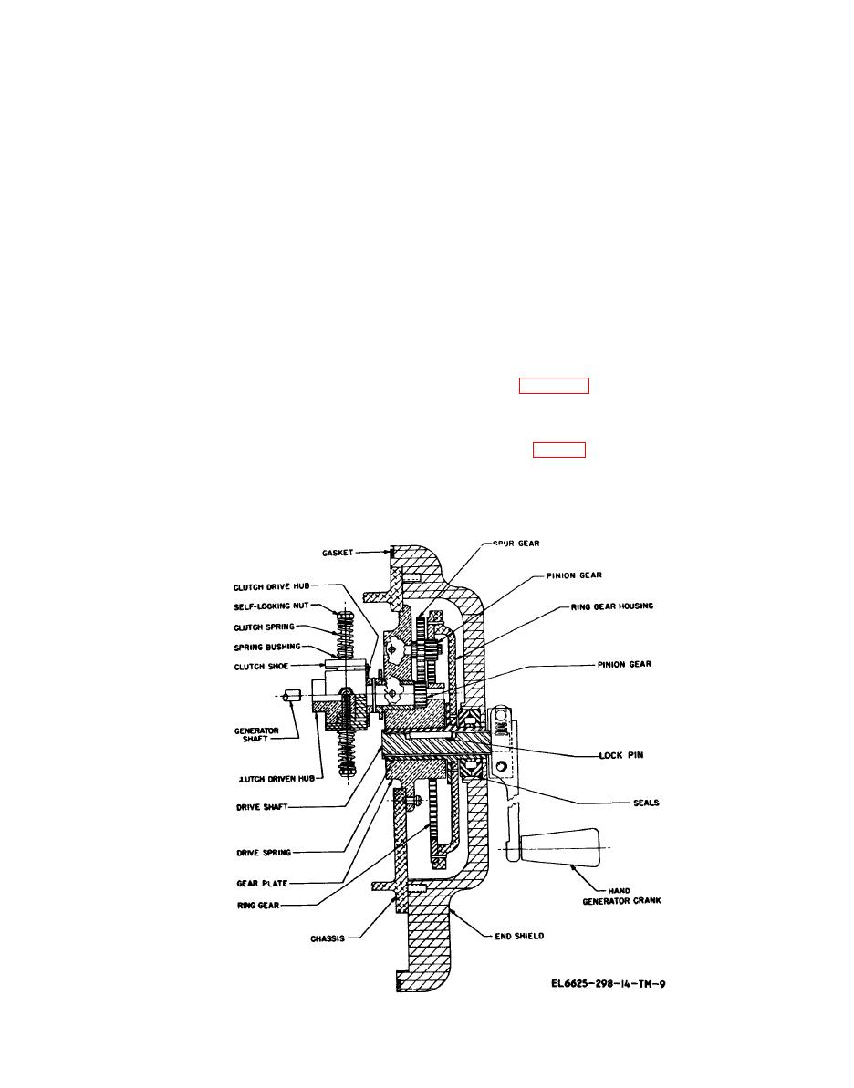
b. The generator drive assembly of ohmmeter is
meter is from O through 1,000 megohms. The
shown in figure 5-1. The generator is driven by a
resistance is indicated by a meter of special design,
hand-operated crank through a gear train and
and the indication given is as near as possible to a
clutch assembly. The clutch assembly is adjusted
true representation of the insulation resistance of
so that it will not slip. On, earlier models of the
the equipment, wire, or cable under test.
ohmmeter (fig. 5-2) when the crank reaches an
5-2. Hand Generator
operating speed of approximately 160 rpm, cen-
trifugal force disengages the clutch shoes from the
a rotating armature in a fixed magnetic field. The
hub in order to maintain constant voltage.
armature has a 39-bar commutator running be-


