TM 11-6625-298-14
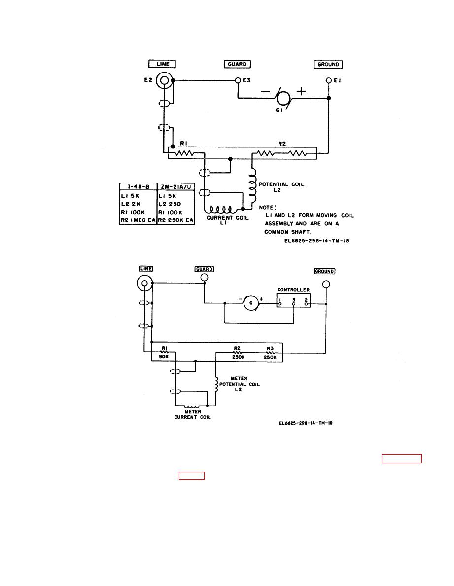
5-4. Resistance Network
5-5. Meter Movement
The resistance network of Ohmmeter ZM-21B/U
consists of one 90,000 ohm resistor, R1, and two
The indicating instrument consists of two coils,
250,000-ohnm resistors R2 and R3 (fig. 5-4). The
potential coil L2, and current coil L1. These coils,
two 250,000-ohm resistors are connected in series
mounted on a common axis and connected so that
between one side of meter potential coil L2 of the
they oppose each other in a definite ratio, rotate
between two pole pieces in a magnetic field. One
force tends to move the indicating pointer toward
(through the controller). Resistor R1 is connected
between one side of meter current coil L1 of the
ZERO on the ohmmeter scale; the other force
ohmmeter and the LINE terminal and acts as a
tends to move the pointer toward INFINITY.
protective resistance to guard against damage
b. Current flows to the indicator through
caused by excessive current flowing in coil L1.
flexible ligaments of practically zero torque which
5-3


