TM 11-6625-2629-14&P
(4) Remove the two remaining screw.
(3) Remove the retaining ring (10) from the
-
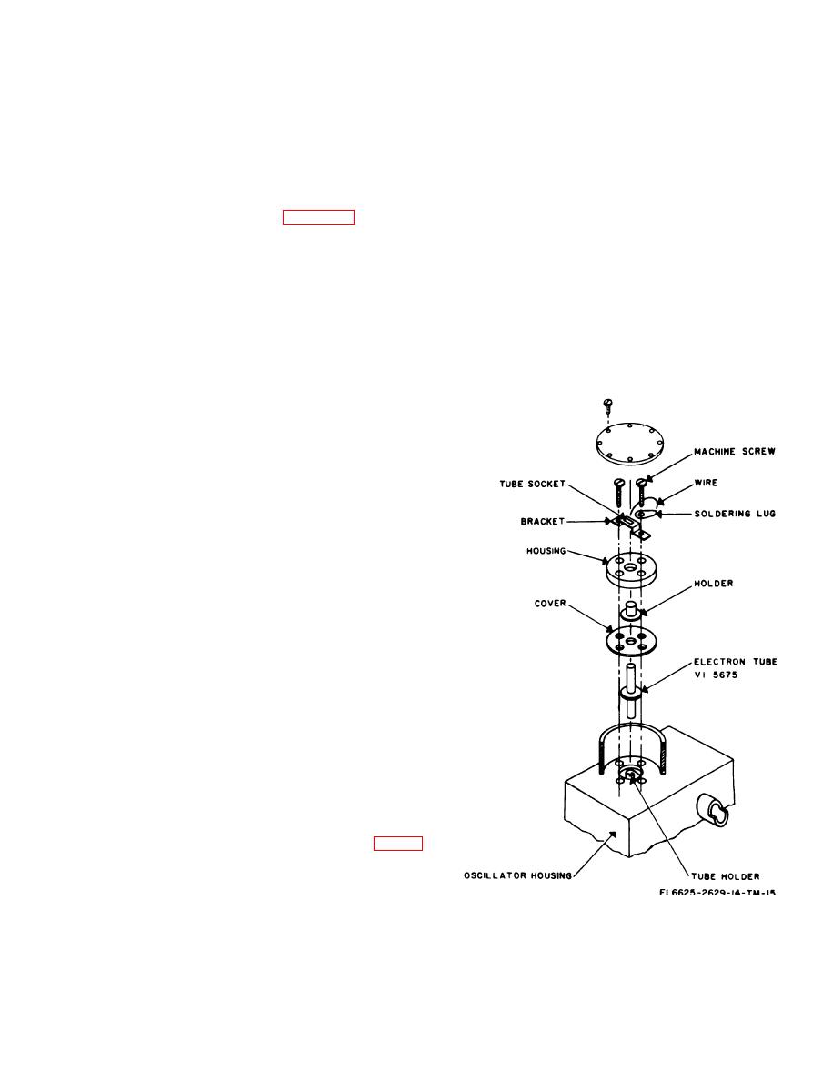
(5) Lift off the housing, the holder, and the
groove in the rotor shaft (9).
cover.
(4) Release the tension on the detent arm (5)
(6) Pull the tube straight up to remove it
by loosening the screw (3) that holds it to the
from the plate contact.
detent bracket (4).
(7) Insert new tube into the plate contact.
(5) Hold the rotor (23) and pull the rotor
shaft (9) out.
(8) Be sure that the grid makes contact with
t h e grid contact mounting of the tuning
(6) Remove the rotor (23).
capacitor.
(7) Remove tube Vl (para 7-20).
(9) Replace the cover, holder, and housing.
(8) Remove resistors R7 (60) and R8 (61)
(10) Replace the two screws that do not hold
from the grid and plate contacts of V1.
the bracket.
(9) Loosen the two setscrews (38) that "hold
(11 ) place the bracket assembly over the
the tuning capacitor (31) shaft to the coupling
tube pins.
(39). Pull out the coupling (39) until it is flush
(12) Replace the two screws that hold the
with the inside of the housing (l).
bracket.
(10) Remove the screws (3), lockwashers (6),
(13) Check the continuity of filament circuit.
and hexagonal nuts (7) that hold the tuning
(14) position the lid and secure it in place
capacitor (31) to the mounting bracket (30).
with 8 screws and lockwashers.
(11) Remove the tuning capacitor (31) and
the plateholder assembly (17), capacitor contact
assembly (28), and the rotor contacts.
b. Reassembly.
(1) Mount the plateholder assembly(17) and
capacitor contact assembly (28) on the tuning
capacitor (31 ).
(2) Replace the tuning capacitor (31) on the
mounting bracket (30); use the screws (3), lock-
washers (6), and hexagonal nuts (7).
(3) Place the coupling (39) over the tuning
capacitor shaft.
(4) Tighten the setscrews (38) on the shaft.
(5) Tighten the screws that hold the tuning
capacitor (31 ) to the bracket (30). Be sure that the
shaft rotates freely.
(6) Replace resistors R7 (60) and R8 (61) to
the capacitor contact assembly (28) an
plateholder assembly (17) contacts.
(7) Replace V1.
(8) Replace the rotor shaft (9) in its original
position.
(9) Push the rotor shaft (9) into position.
(10) Tighten t h e d e t e n t a r m (5) by
tightening the screw (3) attached to the detent
bracket (4).
(11 ) Replace the retaining ring (10) in the
groove in the rotor shaft (9).
(12) With the rotor in position, tighten the
setscrew (24) on the rotor hub.
c. Replacement of Electron Tube VI (fig. 7-6).
(1) Remove 8 screws with lockwashers
holding the lid, then remove the lid that covers
the tube enclosure.
(2) Remove the two machine screws that
Figure 7-6. Disassembly diagram for replacement of tube V1.
hold the tube socket bracket assembly.
( 3 ) Lift off the tube socket bracket
assembly.
7-13


