TM 11-6625-2629-14&P
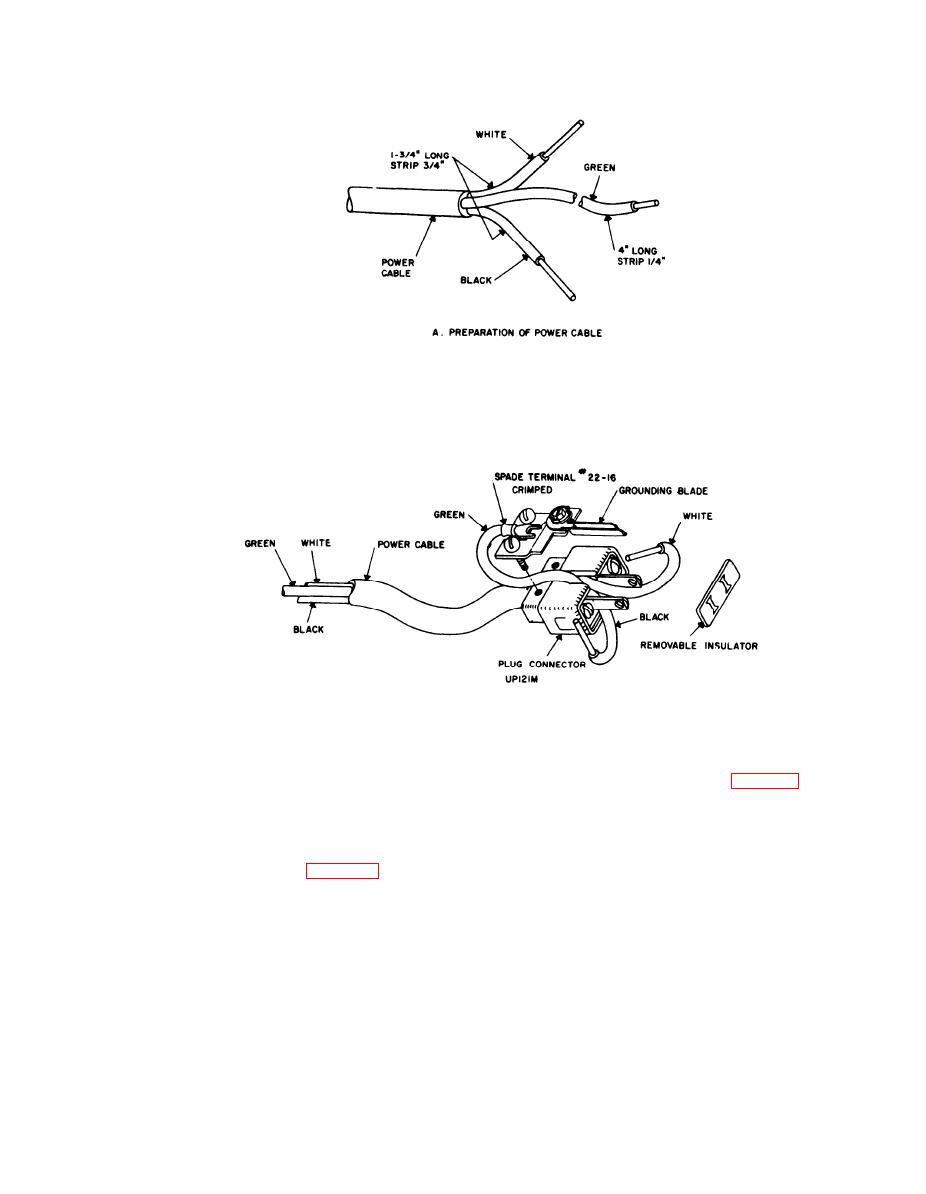
Figure 7-8. Replacement of power plug UP131M,
7-20. Equipment Adjustments
drive mechanism for the tuning capacitor has
If repairs or replacements have been made within
been disassembled, it may be neceasary to adjust
the oscillator unit, it may be necessary to adjust
the gears for optimum mesh. Make this ad-
the shutter or dial on its shaft. Make the ad-
justment as follows:
justments as follows:
(1) Loosen the screws that hold the bracket
to the front panel so that the bracket may be
(1) Rotate the rotor (23) to the position that
positioned. The holes are oversize.
will put the 20- to 55-MHz coil on the rotor (23) in
( 2 ) Move the bracket so that the in-
contact with the tuning capacitor (31).
termediate gear meshes with the dial gear.
(2) Loosen the setscrews (33) on the drive
(3) Hold the bracket in the desired location
sprocket (47).
and tighten the screws. Use a small clamp to hold
(3) Rotate the drive sprocket (47) on the
the bracket.
shaft (46) until the shutter assembly (45) is in the
position for the 20-55 MHz band.
(4) Tighten the setscrew (33) that holds the
drive sprocket (47) to the shaft (46).
7-15


