TM 55-4920-244-14
(2) Install cable and printed circuit
b. Installation.
board assembly (16) on box assembly (18) and
(1) Position printed circuit board as-
secure with screws (17).
sembly (49, fig. 48) on deck (128) and secure
with spacers (53) and screws (50).
(3) Install deck assembly (para. 4-
(2) Solder wiring in bundle to cor-
responding terminals on printed circuit board as-
sembly.
(3) Install deck assembly (para. 4-
c. Deleted.
Figure 4-11. Deleted.
GALVO-2) (Figure 4-8).
a. Reassembly. No reassembly is required
except step
below.
b. Installation.
CAUTION
Failure to provide cover
for the deck may result in
damage from melted sol-
der or hot soldering iron.
(1) Feed wiring through openings
in dust cover and connect to proper terminals in
galvanometers (29) and 69). Provide several
thicknesses of cloth or other suitable cover for
top of deck (128).
assembly.
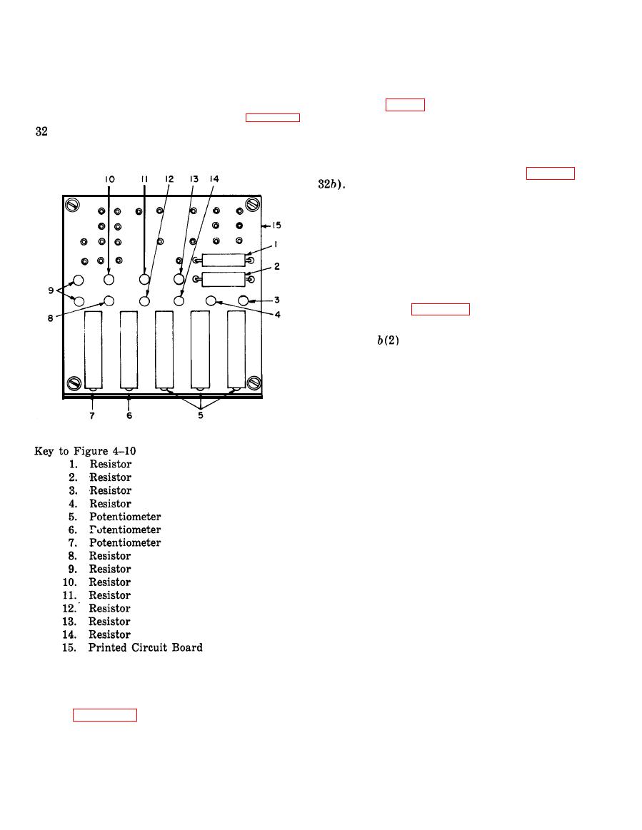
4-40. BH1760 Printed Circuit Board Assembly
a. Reassembly. No reassembly of the
printed circuit board assembly is required.
All data on page 4-33 deleted.
Change 1
4-32


