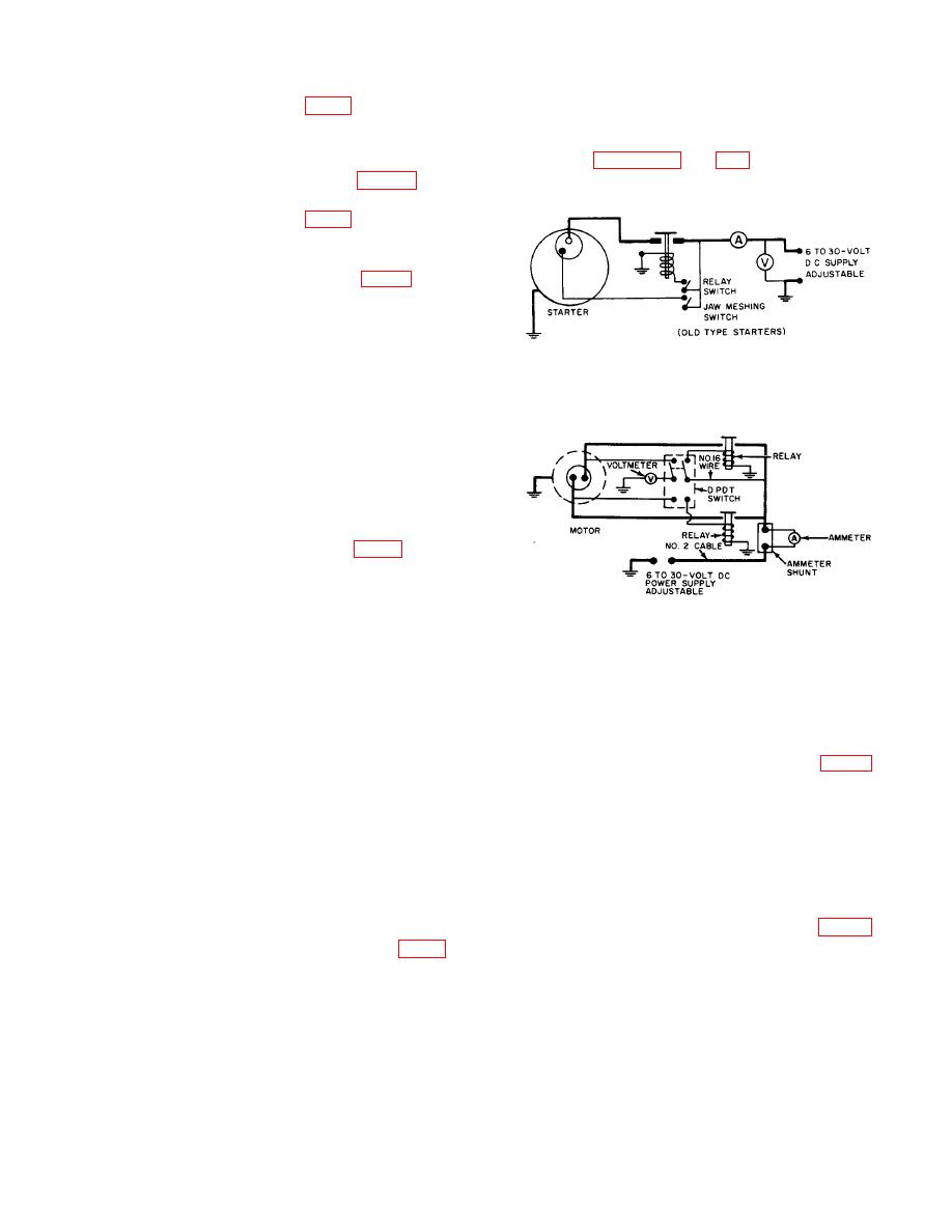
Note: Testing actuators or retraction
(3) Install cotter pins (14, fig. 5) through each
motors requires a different wiring
end of upper pivot pin (15).
setup from that shown for starters.
(4) Install lower pivot pin (16) through base
and frame assembly (31) and through
difference in wiring setup.
mounting support (3, fig.
4) of
torquemeter.
(5) Install cotter pins (14, fig. 5) through each
end of lower pivot pin (16).
be installed on either side of the test stand by
interchanging the flexible drive shaft.
12. INSTALLATION OF STARTER TORQUE TESTER
Figure 6. Typical Wiring Diagram for Testing
Install the starter torque tester as follows:
Starters
a. Mount starter torque tester on a heavy bench or
other firm structure using four mounting bolts.
b. Mount tachometer to bench or a suitable stand
to prevent damage during operation of tester.
c. Connect power source wires to an external
adjustable dc power supply, varying from 6 to 30 volts
and capable of supplying 300 amperes continuously.
d. Connect flexible drive shaft (18, fig. 5) from
tachometer to starter torque tester at tachometer drive
assembly (19).
e. Ground starter torque tester to negative side of
external power source.
Figure 7. Typical Wiring Diagram for Testing
Actuators
Section II. CONTROLS AND INSTRUMENTS
13. GENERAL
15. OPERATOR'S INSTRUMENTS
This section describes, locates, illustrates, and
furnishes the operator or crew sufficient information
attached between either the right or left carrying arm (1)
pertaining to the controls provided for the proper
of the starter torque tester and the base and frame
operation of the starter torque tester.
Careless
assembly (9). The location depends on whether the
operation or improper setting of the controls will cause
starter being tested has left-hand or right-hand rotation.
damage to the equipment. For this reason, it is
The torquemeter measures the torque of the starter in
important to know the function of every control.
foot-pounds.
Three torquemeter assemblies with
different ranges are provided for testing starters,
actuators, or retraction motors.
14. OPERATOR'S CONTROLS
mounted to the bench or a suitable stand.
The
The brake pressure control assembly (4, fig. 2)
tachometer indicates the rotational speed of the starter
is located top center on the starter torque tester. Brake
jaw in either clockwise or counterclockwise direction.
pressure is applied by turning the control cap on the
The tachometer can be connected directly on the starter
brake pressure control assembly. Turning the cap
torque tester for speeds up to 150 rpm; for higher
clockwise will apply pressure to the brake; turning the
speeds, however, the tachometer reduction drive
cap counterclockwise will release the brake.
assembly (3) supplied with the starter torque tester must
be used.
7


