TM 55-4920-231-14
(3) Turn VACUUM selector knob (20) to
30''-10" MANIFOLD ABS PRESS position and
turn knobs (17 and 19) to close valves.
(4) Place case leak valve lever (7, figure 8)
in NOR position.
(5) Make test hose connections (paragraph
(6) Turn vacuum INCREASE knob (17,
CREASE knob (19) to provide the required
stabilized readings (figure 16) on manifold
pressure gage (7, figure 7).
(7) Observe reading on instrument being
tested at each cheek point and record reading on
calibration card (8, figure 7).
(8) Perform the case leak test by turning
knob (8, figure 4) to fully dose external leak
valve (10) at 11 in. Hg reading on manifold
pressure gauge (7, figure 7). Observe reading
on instrument being tested and time for exces-
sive leakage. (Refer to table 3.)
(9) When case leak test is completed,
knob (8, figure 4) to fully open external
leak valve (10).
(6) Make test hose connections (paragraph
(10) Turn vacuum INCREASE knob (17,
38) and start the tester (paragraph 36).
figure 7) to close valve and vacuum DE-
(7) Turn vacuum INCREASE knob (17,
CREASE' knob (19) to open valve, allowing
readings to return to normal when the tests have
CREASE knob (19) to provide stabilized read-
been completed.
ings (figure 14) on airspeed indicator (6, fig-
(11) Stop the tester (paragraph 37).
ure 7).
(8) Observe reading on instrument being
b. Pressure Test.
tested at each check point and record reading on
(1) Perform master instrument test (para-
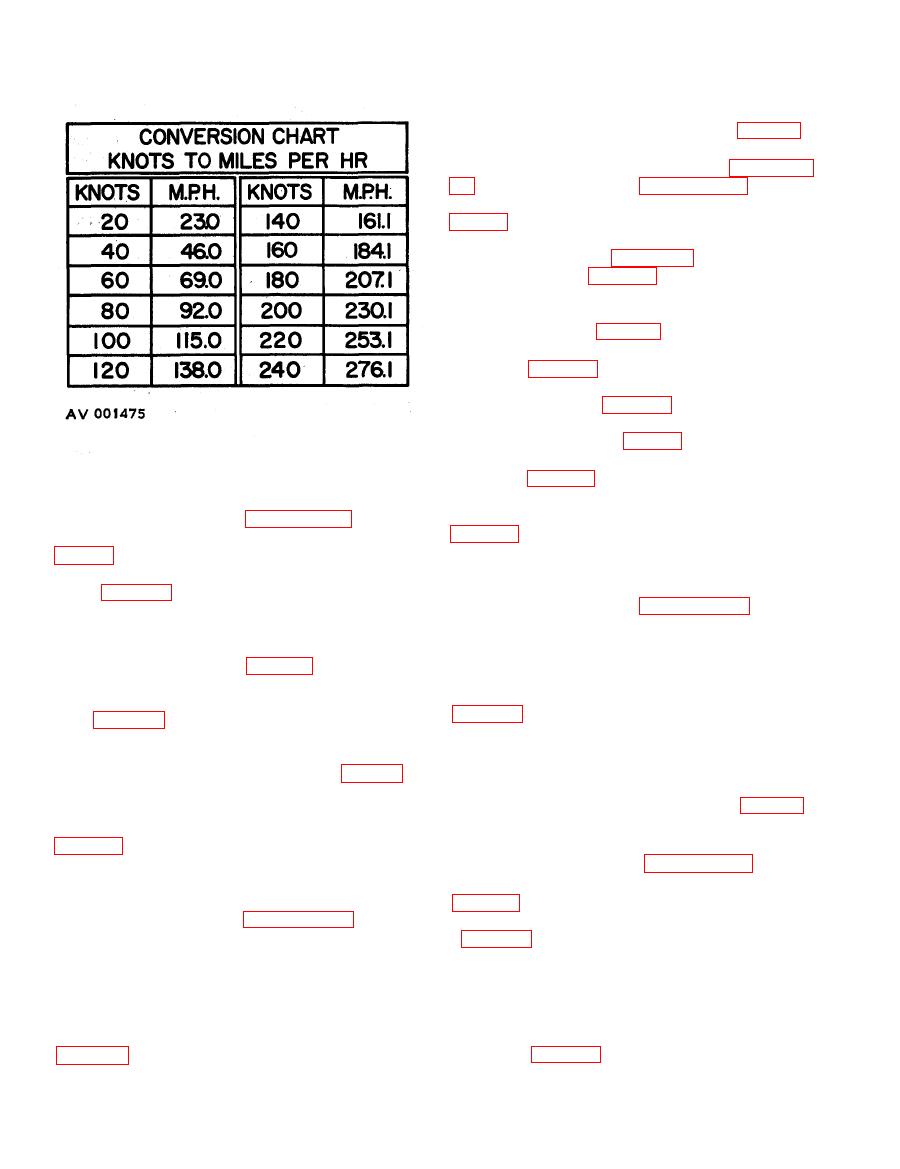
calibration card (8). Refer to figure 15, for con-
graph 39d).
verting knots to miles per hour.
(2) Place VACUUM selector knob (20,
(9) Perform case leak test by turning knob
(8, figure 4) to close external case leak valve
and 19) to open valves.
(10) at 200 knot reading on airspeed indicator.
(3) Turn PRESSURE selector knob (10) to
(Observe reading on instrument being tested and
30''-75" MANIFOLD ABS PRESSURE position
time for excessive leakage. (Refer to table 3.)
and turn knobs (11 and 12) to close valves.
(10) When case leak test has been completed,
(4) Place case leak valve lever (7, figure 8)
turn knob to open external case leak valve (10).
in NOR position.
(11) Turn vacuum INCREASE knob (17,
(5) Make test hose connections (paragraph
38) and start the tester (paragraph 86).
knob (19) to open valve and allow readings to
return to normal when the tests have been com-
(6) Turn pressure INCREASE knob (12,
pleted.
(12) Stop the tester (paragraph 37).
(11) to provide the required stabilized readings
ure 7).
(7) Calibrate the instrument being tested by
a. Vacuum Tests.
observing the readings at each check point and
(1) Perform the master instrument test
recording on calibration card (8).
(paragraph 39e).
(2) Plane PRESSURE selector knob (10,
(8) Perform the case leak test by turning
knob (8, figure 4) to fully close external case
leak valve (10) at 65 in. Hg reading. Observe
and 12) to open valves.


