TM 55-4920-231-14
(5) Place case leak valve levers (3 and 4,
for converting knots to miles per hour.
figure 8) in NOR position.
(8) Perform case leak test by turning knob
(6) Make test hose connections (paragraph
(8, figure 4) to close external case leak valve
38) and start the tester (paragraph 36).
(10) at 200 knot reading on airspeed indicator.
CAUTION
Observe reading on instrument being tested and
Do not allow altimeter reading to go be-
time for excessive leakage. (Refer to table 3.)
low -1000 feet or the rate-of-climb indi-
(9) When case leak test has been com-
cator to exceed 6000 fpm since exceeding
pleted, turn knob (8) to open external case leak
these limits will damage the instru-
valve (10).
ments.
(10) Turn pressure INCREASE knob (12,
(7) Turn pressure INCREASE knob (12,
DECREASE knob (11) to open valve allowing
instrument readings to return to normal when
tests have been completed.
ings by adjusting pressure DECREASE knob
(11) Stop the tester (paragraph 37).
(11).
(8) Observe readings on instrument being
b. Vacuum Test.
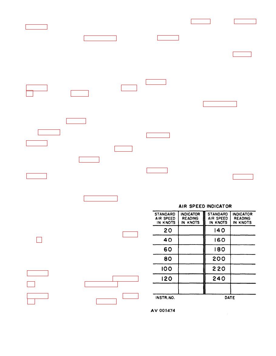
tested at each check point and record on cali-
(1) Perform master instrument test (para-
bration card (8, figure 7).
graph 39h).
(9) Perform case leak test by turning knob
(2) Place PRESSURE selector knob (10,
(8, figure 4) to fully close external case leak
valve (10) at -1000 ft. reading on altimeter (3,
(11 and 12) to open valves.
(3) Turn VACUUM selector knob (20) to
tested and time for excessive leakage (table 3).
AIRSPEED VACUUM SETTING and turn
(10) When case leak test has been com-
knobs (17 and 19) to close valves.
pleted, turn knob (8, figure 4) slowly to open
(4) Place case leak valve levers (3, and 4,
external case leak valve (10).
figure 8) in NOR position,
(11) Turn pressure INCREASE knob (12,
(5) Open rear access panel (11, figure 4)
DECREASE knob (11) to open valve and allow
and turn knob (14) to open safety valve (13).
instrument readings to return to normal when
the tests have been completed.
(12) Stop the tester (paragraph 37).
a. Pressure Test.
(1) Perform master instrument test (para-
graph 39g).
(2) Place VACUUM selector knob (20, fig-
ure 7) in OFF position and turn knob (17 and
19) to open valves.
(3) Turn PRESSURE selector knob (10) to
20-250 KNOTS position and knobs (11 and 12)
to close valves.
(4) Place case leak valve levers (3, and 4
figure 8) in NOR position.
(5) Make test hose connections (paragraph
(6) Turn pressure INCREASE knob (12,
just pressure DECREASE knob (11) to stabilize
the readings.
(7) Observe reading on instrument being
tested at each check point and record reading on


