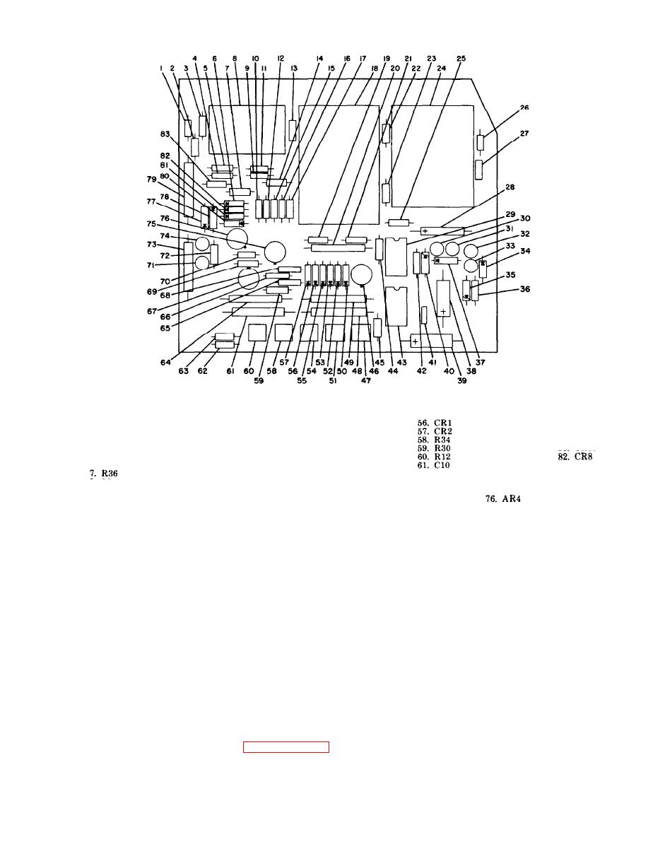
TM
11-6625-539-14-4
EL6625-539-14-4-TM-18
1.
R10
45.
R4
78.
CR11
67. AR3
12. R33
23.
R1
34.
CR15
2.
R16
79.
C8
46.
AR1
68. R26
13. C1
24.
S2
35.
CR12
3.
R28
80.
CR14
47.
R3
69. R23
14. R42
25.
R2
36.
CR12
4.
R40
81.
CR13
48.
C5
70. R17
26.
R37
15. R19
37.
CR7
5.
R39
49.
C3
16. R22
71. Q1
27.
C6
38.
C13
6.
CR9
50.
CR6
83. R27
72. R21
17. R25
28.
C2
39.
C12
51.
R6
73. C11
62.
R7
18. S1
29.
Z1
40.
CR16
8:
S3
52.
CR5
74. Q2
63.
R14
19. R9
30.
Q6
41.
C7
53.
CR4
64.
C9
9.
R43
75.AR2
20. C6
31.
R31
42.
R29
10.
R32
54.
R8
65.
R20
21. R18
32.
Q5
43.
Z2
11.
R41
77. CR10
55.
CR3
22. R5
66.
R31
33.
Q4
44.
R11
Section V. GENERAL SUPPORT TESTING PROCEDURES
7-13. General.
order given. Make sure that you set the controls
accurately as indicated.
This section describes all tests required to make
to determine that the transistor test set is func-
tioning properly in all modes of operation. To
totally check out the unit, perform all tests. If the
7-14. Physical Tests and Inspection
operation of the unit in any particular function is
questionable, that function alone can be checked.
a. Test Equipment and Materials. None.
Before performing any other operation tests,
b. Test Connections and Conditions. Remove
make sure the battery output is adequate as
cover from case of test set.
indicated by the battery test in paragraph 715.
During testing, follow the procedural steps in the
c. Procedure.


