TM 11-6625-298-14
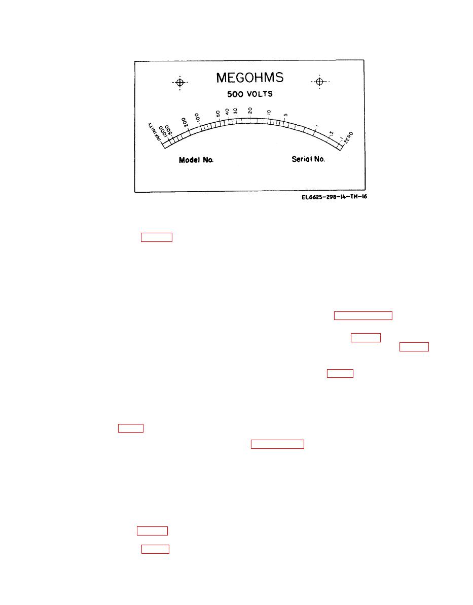
Figure 6-4. Meter scale.
6-8. Replacement of controller
CAUTION
Be careful not to damage the coil pivots or
the pointer.
b. Disconnect and tag the three wires leading to
c. Back off the upper jewelled bearing, and
the controller.
carefully withdrew the armature from the magnet.
c. Remove the two screws holding the controller
d. Install a new armature, and replace the upper
to the chassis.
jewelled bearing. Reconnect the ligaments and
d. Reconnect the wires to the replacement
terminals to the moving coil assembly.
controller and replace the screws that fasten the
e. Replace the meter and meter scale (pars 6-7).
controller to the chassis.
Calibrate and mark the new meter scale according
6-9. Replacement of Hand Generator
to instructions given in paragraph 6-16.
a. Remove the chassis and chassis cover.
b. Remove the two snap buttons on the un-
derside of the chassis.
c. Disconnect the leads from the generator
and remove the brushes.
brush-holder terminals.
c. Remove the two self-locking nuts at the front
d. Remove the self-locking nuts, two of which
end of the generator (fig. 6-1).
can be reached from the top of the chassis and the
d. Withdraw the armature, and replace it with a
other two through the holes on the underside of
new one.
the chassis from which the snap buttons have been
e. Place the end bell in position, and replace the
removed.
self-locking nuts.
e. Withdraw the generator from the chassis.
f. Replace the generator brushes and brush
f. Knock out the taper pin that retains the
cape.
clutch driven hub (fig. 5-1), and remove the hub.
g. Reinstall the generator as instructed in
to the shaft.
6-12. Replacement of Terminals
h. Place the new generator on the chassis, and
When replacing terminals be sure to install all
replace the self-locking nuts. On the underside of
washers and insulator bushings in the order in
the chassis, return the snap button to the holes
which they were originally installed. Observe this
from which they were removed.
precaution especially in the case of the line ter-
i. Reconnect the leads to the generator brush-
minal; this is the terminal on which the guard ring
holder terminals.
is mounted.
6-10. Replacement of Meter Armature
a. Remove the rectangular nickel-plated bezel
b. Disconnect the ligaments and terminal from
from the top surface of the meter window.
the moving coil assembly (fig. 5-5).


