TM 11-6625-261614
c. Reference input pin 1 is switched externally
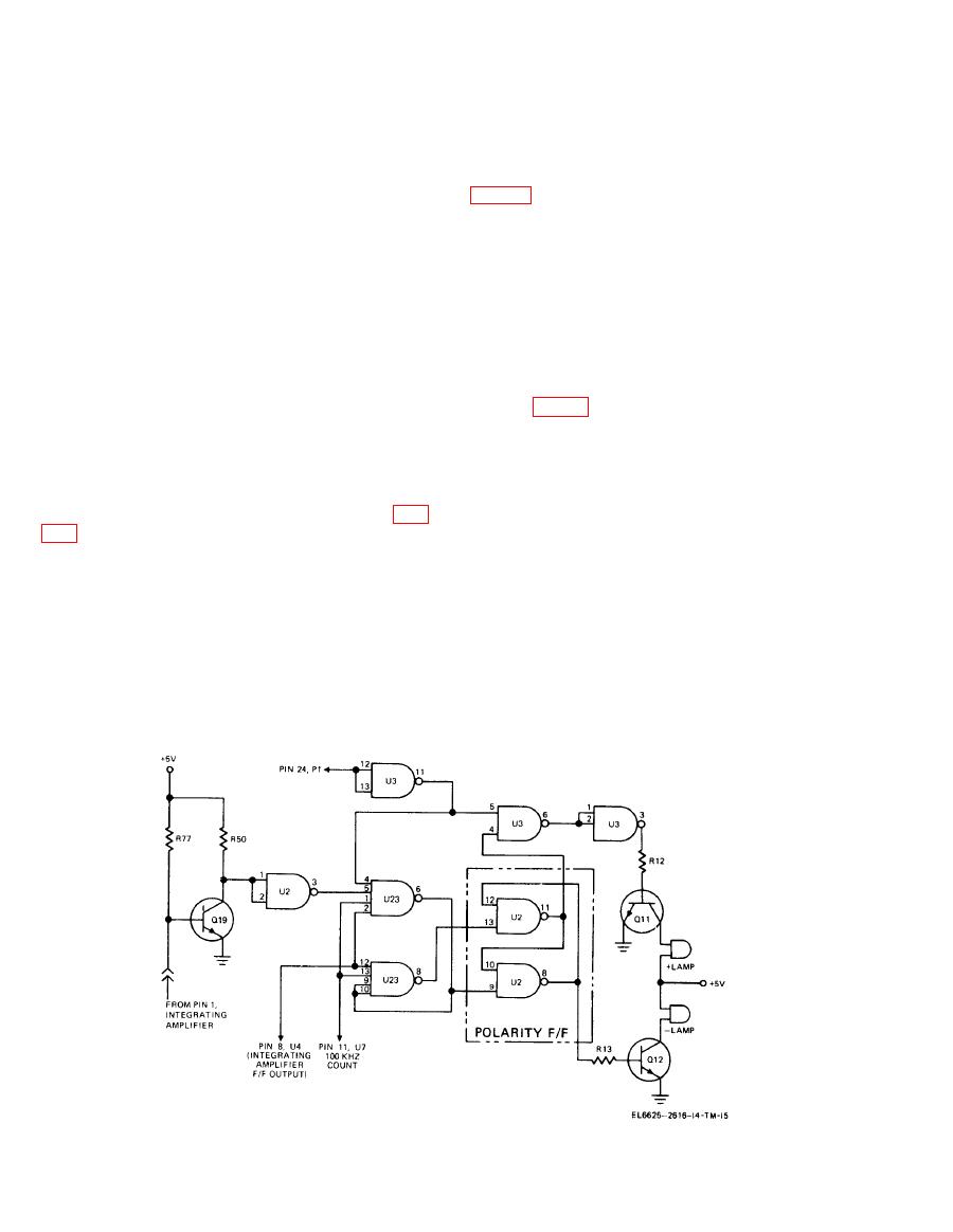
of U2, pins 8, 9, 10, and 11, 12, 13) which drive
by the front panel ratio switch to either the
buffers (U3, pins 1, 2, 3, and Q11, Q12) capable
internal + 10-volt reference or in the ratio mode to
of illuminating the proper polarity lamp.
external bipolar voltages.
b. The polarity signal at the collector of Q19
d. Q7, Q8, Q9, and Q10 act as polarity reversing
Buffer output (pin 3) feeds a gate signal to pin
switches which are controlled by Q4, Q5, and Q6,
5 of U23. Pin 4 of U23 is held on continuously by
connected in a differential amplifier configura-
U3 (pins 11, 12, and 13) which is used in con-
tion. Differential outputs at Q4 and Q5 collectors,
junction with an ac converter. Pin 2 is gated by
gate CR2, CR3, CR4, and CR5, switching the
the 200-millisecond pulse from the output of the
proper transistor pairs, Q7-Q9 or Q8Q10. The
input integrating flip-flop (U4, pin 8) which also
outputs of Q7 and Q9 are fed to U3. The outputs
gates on by pin 11 of U7. The timing insures an
of Q8 and Q10 are fed to U4. U4 feeds the
optimum sampling of signal polarity.
differential input of U3, resulting in a unipolar
output at pin 6 of U3 for an input of either
polarity at pin of the reference supply. Q3 acts
as a buffer for U3 and drives the reference cur-
rent generator U2Q2.
a. The range selecting circuits of the AN/GSM
64A may be operated by a front panel pushbutton
or, set to automatically selected the proper range
by depressing the auto-range pushbutton. In the
a. The polarity indicating circuit begins at the
manual mode, the range circuits are actuated by a
output of U1, in the integrator amplifier (fig.
pulse generated when the range change push-
button is depressed, Range changes step from the
bridge circuit CR1, CR2, CR3, and CR4, the polar-
highest range to the midrange, to low range and
ity indicating circuit input, R8, CR5, CR6, and
then to the highest range again. In the automatic
Q7. R8, CR5, and CR6 protect differential am-
mode, an up-range signal causes the automatic
plifier Q7 from excessive signal out of U1. The
circuitry to select the highest range. A down-
output of Q7 appears on pin 1 of the integrator
range signal will cause the circuitry to select the
amplifier and is connected to the base of Q19.
next lower range.
The state of Q19 determines which polarity lamp
will light. The output of Q19 and timing signals
from the digitizing circuits gate two sections of
the presence of an up- or down-range signal.
U23. U23 then controls a flip-flop (two sections
An up-range signal is generated when the fre-
Figure 5-8. Polarity circuits, simplified
schematic diagram.


