TM 11-6625-261614
beginning of each reading and remains on until
a count of 10,000 occurs. If the 10,000 count oc-
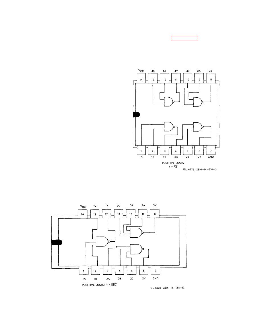
The logic diagrams in figures 5-10 through 5-18
curs earlier than the storage display pulse, flip-
are provided to assist the repairman in under-
flop U1 resets and prevents U5, pin 8, from
standing the internal circuitry of the integrated
down-pulsing.
circuits and thereby their effect upon overall
functioning of the AN/GSM-64A.
e. The up-down outputs of U5 are fed to bi-
directional counter U1 on the signal condition-
ing board via pins 8 and 9 of J16. Counter U1
outputs are decoded and feed range relay driver
transistors Q2 and Q3 which actuate relays K1,
K2, or neither. Counter outputs are also fed to
pins 11 and 12 of J16 from which decimal driver
U22 (located on the main circuit board) decodes
the range information and illuminates the pro-
per decimal readout.
f. In the ratio mode, U22 receives a third
input at pin 3 from gate U4 (pins 4, 5, and 6)
located on the signal conditioning board. U4
is actuated by front panel ratio switch, S8. The
third input produces a decimal shift to corre-
spond to the percentage reading required in the
ratio mode.
powered through collector supply transistors
Q1 and Q4. In the ac mode (if an ac converter
has been installed ), Q4 does not receive base bias
through R12 or R13, which cuts off Q1 and
prevents K1 and K2 from operating.
2-input positive nand gate logic diagram.
gate logic diagram.


