TM 11-6625-539-14-3
ALIGNMENT PROCEDURES
(3) Set the function switch to OHMS E-B.
Under normal conditions, the test set will maintain
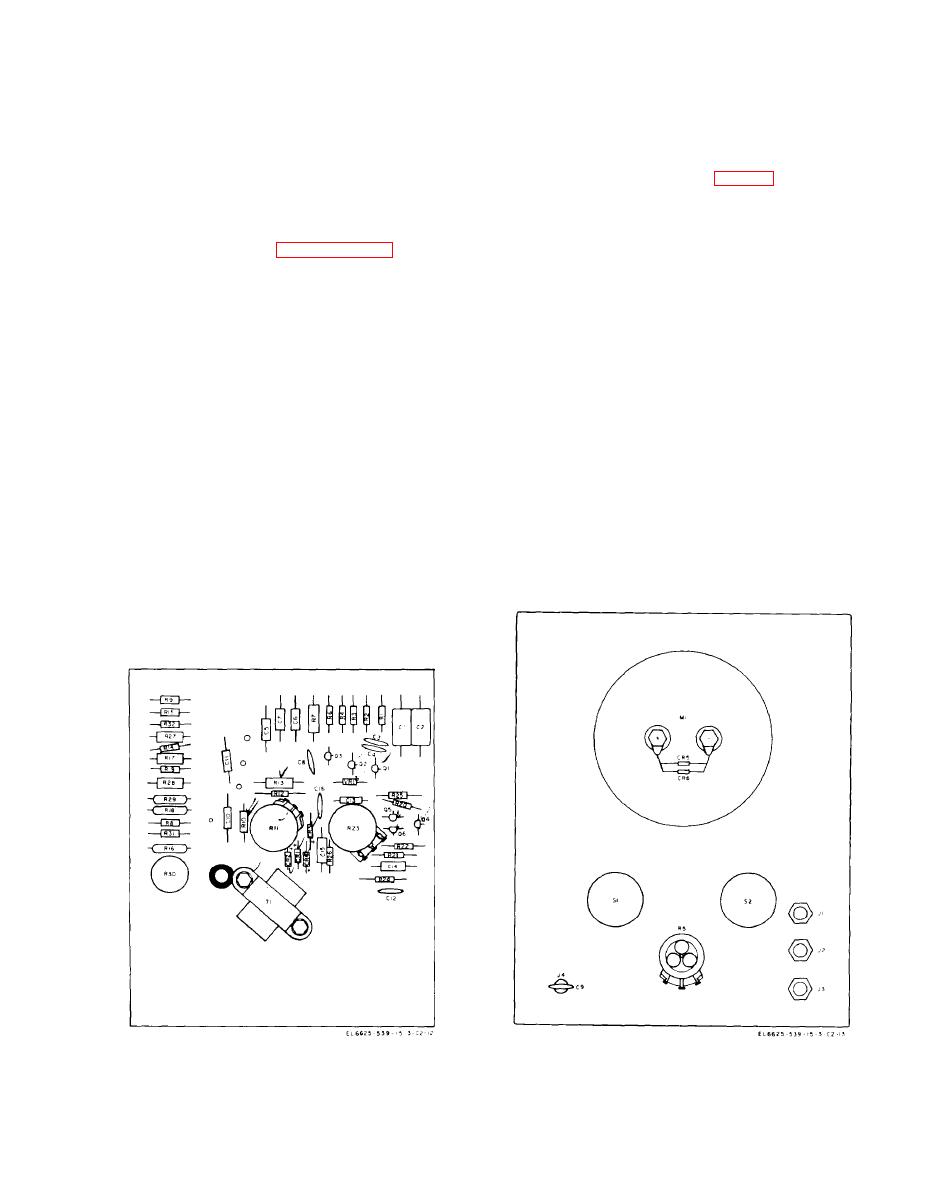
(4) Adjust resistor R11 (fig. 7-1) so that the
the factory alignment over a long period of time.
meter pointer indicates full scale on the OHMS
scale.
It is necessary to realign the test set if any com-
(5) Place the 100-ohm, 1 percent, l/Z-watt
ponent except the batteries is changed. Alignment
resistor between the E and B jacks cm the front
procedures are given in paragraphs 7-2, 7-3, and
7-4.
panel.
(6) Adjust resistor R30 so that meter Ml indi-
cates 100 ohms.
a. Set the polarity switch to OFF.
(7) Remove the 100-ohm resistor, and check
to see that the meter pointer indicates full scale.
b. Adjust the meter zero adjustment screw located
If the Meter pointer does not indicate full scale,
directly below the base of the pointer for a 0 meter
repeat the procedures in (2) through (6) above.
indication.
a. Test Equipment Required. An ME-30(*) U is
a. Test Equipment Required. The only test equip-
required.
ment required is a 100-ohm. 1 percent, -watt
resistor.
b. Procedure.
(1) Disconnect the unit from the case by re-
b. Procedure.
moving the four panel screws.
(1) Disconnect the unit from the case by re-
(2) Set the polarity switch to FWD PNP.
moving the four front panel screws.
(3) Set the function switch to F. E. T. CAL.
(2) Set the polarity switch to FWD PNP.
Change 2


